Prudent planning and realization of cranes and overhead conveyor systems
Cranes and overhead conveyor systems are widely spread throughout the industry. But which advantages and disadvantages do they have compared to other conveyor systems? Which types exist? How can such systems be planned? All these questions will be answered in this article.

Applications of cranes and overhead conveyor systems
Cranes and overhead conveyor systems are conveyor systems that are required for the material flow. On the one hand, they serve for transport and, on the other hand, they are used to handle heavy loads. But how to classify such systems? The diagram below gives a brief overview:
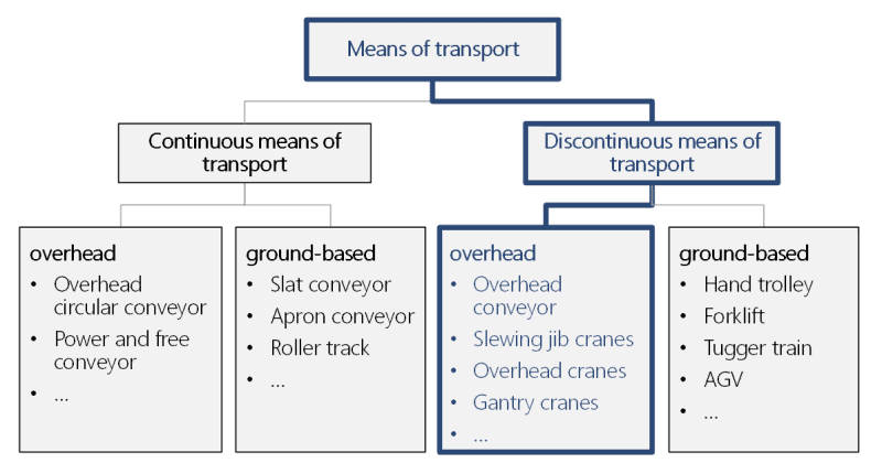
Which are the advantages and disadvantages of overhead discontinuous conveyors, and which are their fields of application?
Advantages:
- Discontinuous transport possible
- Can be used at different working levels
- High flexibility
- Transport above the working and production levels; no or little footprint
- No excessive investments required
Disadvantages:
- Can only be used for low or medium conveying capacities
- No continuous transport possible
- High expenditure of controlling and automation
- Main areas of application are small and medium-batch production
Types of overhead discontinuous conveyors
Please find below an overview of the different types of overhead discontinuous conveying systems.
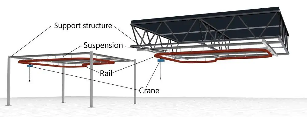
Overhead conveyor systems
Overhead conveyor systems are rail-mounted, separately moving or driven conveyor systems. The linear transport is performed in circular or reversing mode. Overhead conveyor systems are mounted often directly on the supporting structure of the building. In case the load bearing capacity of the building is not sufficient, a specially designed steel construction can also be used for suspension of the overhead conveyor system. Overhead conveyor systems are dimensioned for the most varied payloads.
Function: Point to point transport
Transport distance: Short, medium, long
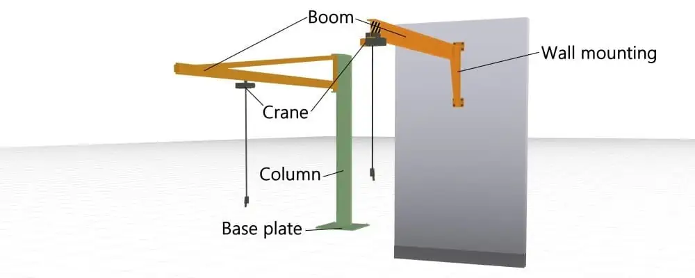
Slewing jib cranes
The crane category of slewing jib cranes includes pillar-mounted slewing jib cranes and wall-mounted slewing jib cranes. Terms such as ‘derrick’ or ‘pillar-mounted slewing crane’ are used as synonyms for the term ‘pillar-mounted slewing jib crane’. For increased flexibility, slewing jib cranes can be designed for different load bearing capabilities, slewing ranges, and radii.
The pillar of the pillar-mounted slewing jib crane requires an installation area. Wall-mounted slewing jib cranes can be mounted on walls, columns or on the equipment.
Function: Area-wide transport
Crane footprint: Small, medium
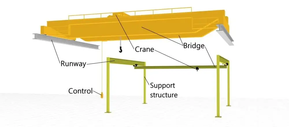
Overhead cranes
Overhead cranes, commonly called bridge cranes, exist in different sizes and designs. The terms ‘suspension crane’ or ‘underslung crane’ are used as synonyms. A distinction is often made between single girder underslung cranes and double girder underslung cranes. The double girder underslung crane is the ideal choice for higher payloads which may amount up to several hundreds tons. The crane bridge travels on the crane runways which are often mounted directly on the columns or pillars of the building, primarily in the case of larger systems. Smaller systems are, however, fixed on the roof supporting structure or on specifically designed steel constructions. Contrary to the slewing jib crane, the crane radius of overhead cranes is not round, but rectangular.
Function: Area-wide transport
Crane footprint: Small, medium, large
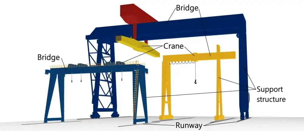
Gantry cranes
In contrast to overhead cranes or suspension cranes, the crane runway of the gantry crane is installed on the floor. The supporting structure is mobile and usually guided in two parallel rails. There are also gantry cranes with freely traveling wheel frames. Gantry cranes can be designed in very different dimensions, depending on the requirements.
Function: Area-wide transport
Crane footprint: Small, medium, large
Planning cranes and overhead conveyor systems
Planning conveyor systems is part of the iterative factory planning process. Iterations result from separate planning of the different planning objects. The systems and the layout of the production main process are planned in first iterations, and the systems of the peripheral processes, such as the conveyor systems, are planned in further iterations. Furthermore, iterations are required due to the increasing level of detail of planning solutions. Result of an iteration in the factory planning process is usually a layout.
1. Developing an overall layout
The planning of conveyor systems always starts out from layout variants of layout objects of the production main process, for example production sections, machines, systems, and workplaces. In this context, it is imperative to take into account the material flows. The types of conveyor systems are predefined in the material flow analyses. The conveyor system is selected in accordance with the following aspects:
- Service program – type and number of the items to be transported
- Layout – transport routes, restrictions in respect of the building, etc.
- the relevant standards, regulations or ordinances where applicable – DIN EN or ISO standards, workplaces ordinance, etc.
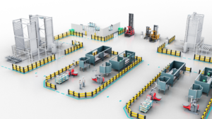
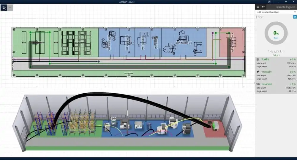
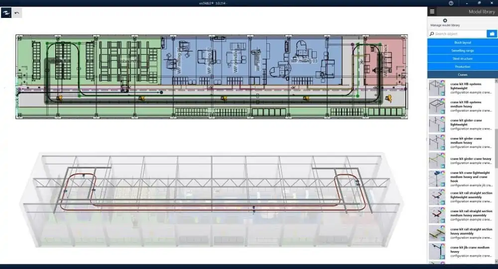
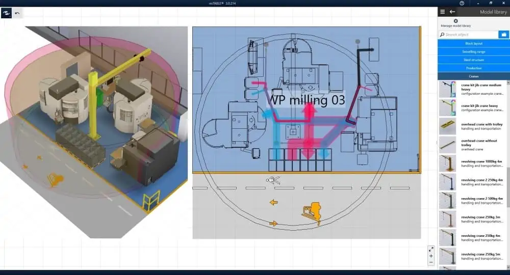
The illustrations below show layout variants as they are developed as prerequisites for designing conveyor systems.
2. Designing conveyor systems
The conveyor systems are designed in the second step. It is paramount to verify the feasibility and to define the routes or positions of the conveyor systems. This step is often performed by a specialist planner of the company operating the conveyor systems.
Planning of the load suspension devices is paramount when working with overhead conveyor systems. In particular, the load bearing capacity of the hall supporting structure (pillars and roof supporting structure) is to be checked in particular, in the case of suspension crane and overhead systems. Specialist planners like architects or structural engineers are to be involved where necessary, and appropriate standards are to be observed, for example DIN EN 1993-1-1, DIN EN 1993-6. If the structure of the building does not permit the suspension of the loads, mounting on pillars in combination with steel constructions should be taken into account.
The main objective of designing the routing or arrangement of the crane runways, crane rails and slewing jib cranes is to specify the work areas and to ensure the feasibility in respect of collisions and interfering contours. The steel constructions are also designed with these objectives in mind, because in particular, the steel pillars constitute layout-relevant interfering contours. It is not decisive here to specify the type and dimensions of double-T girders exactly, for example, but rather to conceive possible pillar positions in advance and to fix them in the layout.
Designing cannot be performed without layout. At this point, however, the difference between designing and constructing should be mentioned. Designing is usually performed in the layout planning software, independently of the manufacturer. Details of the construction are as less as important as exact dimensioning of the crane components. A layout planning software with predefined, module-based, easy-to-operate library elements should be used to enable the specialist planner designing conveyor systems, without requiring him to be a design engineer or specialist for conveyor technology.
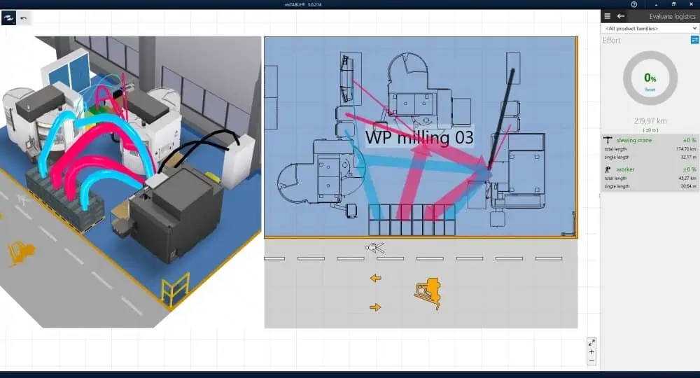
Conveyor systems designed by way of a layout planning system are shown in the illustrations below.
3. Tendering and awarding the contract
Overhead discontinuous conveyors: Planning and realizing cranes and overhead conveyor systems prudently
This phase is focussed on transferring the concept into a performance description with the objective to tender the desired system and request quotations. The quotations are then to be evaluated, manufacturers to be selected, and contracts to be awarded.
The concepts and requirements are usually described by way of requirement specifications. The more exact the inquiries to the manufacturers are formulated, the simpler will be the subsequent verification and comparison of the quotations. Therefore, the requirements and all technical data are to be described as exactly as possible. Important information are for example
- the routing/lengths of the crane rails and crane bridges
- payloads in kg or t
- the dimensioning of the desired swiveling ranges
- radii of the crane systems
- lifting heights
- descriptions of the desired lifting devices or lifting tackle and workpiece holders, for example, manual vs. electrical chain hoist, vacuum lifters vs. crane hooks, and so forth
In particular, geometrical correlations cannot always be described simply and unambiguously by way of requirement specifications. To avoid misunderstandings, a 3D model of the concept should be passed onto the manufacturers. Furthermore, it is recommended to fix appropriate interface formats to be able to exchange models between the customer and the system manufacturer, together with the inquiry or within the framework of the offer phase.
4. Detailed planning and implementation
The awarding of the contract is followed by the detailed planning which is usually performed by the system manufacturer. Paramount is the exchange between customer and contractor. The factory model kept by the customer should be provided with current plan versions of the detailed planning at regular intervals. Within the course of this process, the concept model is replaced by the model from the system manufacturer, and requests for modifications are sent by the customer to the system manufacturer. This iterative process should be conducted as simply and efficiently as possible.
Then the system will be realized which is to be monitored by the customer accordingly, including comparison against the offer. The system can start production after its implementation and release.
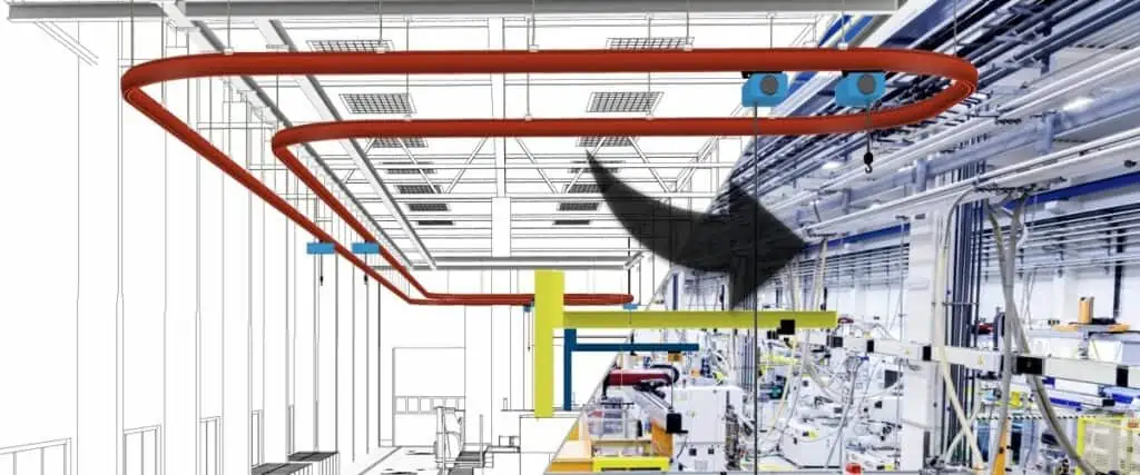
The next visTABLE® update that will be performed in the next time includes an extension of the crane catalog by a straightforward modular crane construction kit, which was also used to create the layout cutouts represented in this article.