What is the benefit of having our whole factory layout in 3D? No-one will ask that question in such simple terms. But there are indeed many simple questions which float around in the mind; especially if you are responsible for the assessment of investments in digital factory planning.
But is the question perhaps already obsolete? After all, this is the 21st century and the fourth industrial revolution is in full swing. Precisely for this reason, we would like to shine a light on some of the practical aspects, and show you how it is done.
The typical starting point in factory layout planning
Unlike many other areas, factory planning does not place digitization as such in the foreground. Formally speaking, most production layouts are already digital. There are few companies that have no CAD factory layout plan and a proper design process and software for it.
The real issue today is: How can the existing data models be made fit for the future? A third dimension seems to be the minimum requirement. And so almost every SME manufacturer will be asking:
What do we need to progress from 2D drawings to a 3D plant layout?
The answer will inevitably lead to software for factory planning, and thus to the demands which are placed on such software. This will normally mean more than just the incorporation of a third dimension:
- How quickly can I receive evaluations of the current factory layout, e.g. floor space utilization or transport complexity?
- Can I show potential customers how material flows are implemented in our production? Or will they even expect this from me (keyword: IATF 16949)?
- Do planning teams need a fast and uncomplicated means to sketch and evaluate the impact of replacement investments or purchase new production equipment?
- Do I want to be able to visualize new ideas for a plant layout without involving external consultants; perhaps even with 3D illustrations for my staff and management colleagues?
If the last two points are relevant, then it is unlikely that you would choose software without 3D capabilities. A 3D plant layout is also simply modern. Or in other words: There is practically no future for factory planning without 3D. Not least because 3D is also establishing itself in industrial construction under the heading BIM. That was still very different from years ago. Today, discussions on 3D planning are not a question of whether, but rather of how.
Three steps to get a 3D plant layout
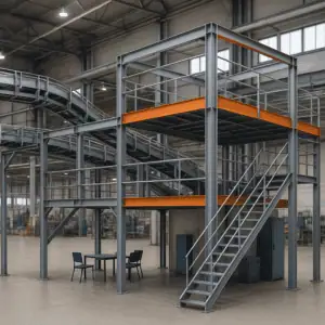
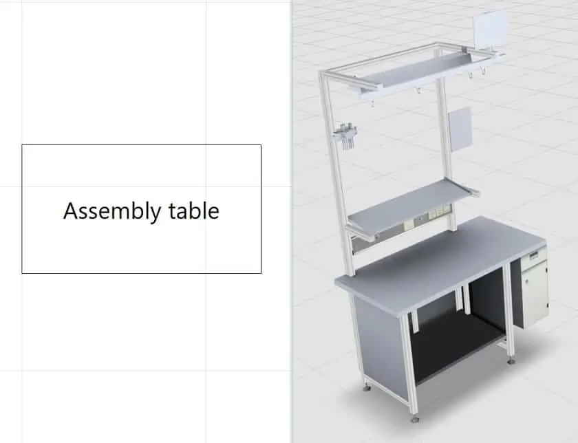
Questions relating to different practical approaches are brought to the fore as soon as you gather your first experiences with 3D. That is when you gain a certain feeling for the aspect of complexity. If we take a simple assembly table, for example, a plain rectangle is generally an adequate description in a 2D system. In 3D, however, it is necessary to consider also the supporting frame, a possible superstructure, the table height, a footrest, etc. All this can be seen in a 3D model. The information density of a 3D plant layout is much higher.
Accordingly – keeping an eye on the aspect of complexity – it is important to include only the relevant 3D information in the layout. Everything else can be left in abstract form. In practice, however, it is this simple rule which presents the greatest difficulties. We will come back to this in steps 2 and 3.
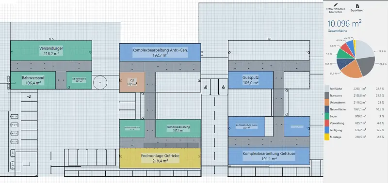
Step 1: Lay the foundation – the “flat” master layout
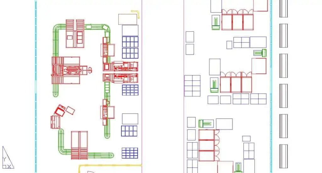
One proven approach is to first create a 2D master plan on the basis of existing 2D CAD hall plans (usually available in DWG format). This plan depicts all departments and production, logistics, or storage areas as simple blocks. It is also possible to combine several existing 2D layouts. The result is a 2D background; the 3D blocks are then simply placed on this background. This also provides an immediate design idea of floor space requirements.
The definition of functional areas creates a general overview, i.e. floor space planning. An area-type concept aids an assessment of floor space use. A simple balance divided into production, assembly, transport, storage, and auxiliary areas is here often sufficient.
The elaboration of such a simple master layout already strengthens awareness of your own data situation. After all, the database relating to the machines installed equipment, and everything else which is necessary for meaningful 3D factory planning is generally far from comprehensive. It often also contains significant errors. Appropriate 3D data are usually lacking even for newer machines. Modern 3D laser scan technologies and the 3D modeling expertise of specialist providers enable gaps in the 3D data to be filled, but that costs both time and money. For that reason alone, you should not be tempted to do everything in 3D, at least not straight away.
Step 2: Use of 3D model libraries
For the second step, a 3D model library is useful. This will ideally include performance-optimized 3D models of elements that are to be found in many typical factory layouts. These include
- assembly equipment (tables, cells, or lines, including material staging),
- storage equipment (e.g. pallet or shelf racks, shuttles, conveyors) and
- typical manufacturing technologies such as SMT or mechanical processing.
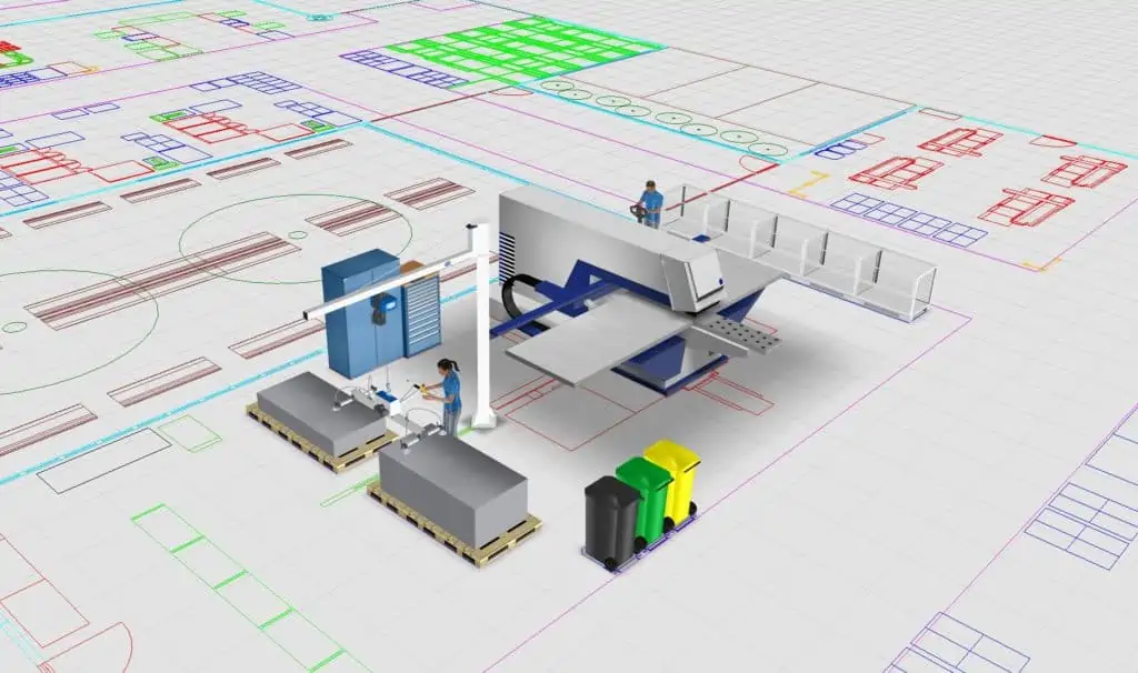
The use of representative elements is often sufficient. In other words, models can be taken to depict a whole range of similar objects. One and the same steel cabinet, for example, can be used in different colors to indicate cabinets with different functions. It is similarly often enough to use the same 3D model for cranes from different manufacturers. Extensive libraries may contain precisely distinguished models.
Tip: Ready-to-use plant layout software will already contain many 3D models. You can quickly create a 3D layout and visualize your plant this way. But it is important that it allows the user to import further models. In this way, the pool of available models can be expanded continually from different sources.
Parametric models add to the flexibility of modeling. This refers to models where individual components can be modified. Building block kits are another practical solution. They can be used to design all kinds of shelf systems, workstations, crane installations, etc. for your 3D plant layout. Such kits are also very useful for elements of the production building, such as platforms, shopfloor offices, or control centers.
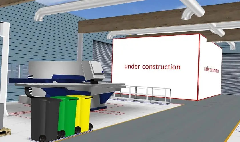
Minor differences in size between a library model and the desired element can be compensated by scaling. If the differences are greater, placeholders are used: Unicolor cubes, polygon shapes, or cylinders, for example. They are initially added to a layout in place of a more precise 3D model. That is fast and comes with a useful side effect: It is visible at a glance, where further work on the digital 3D plant layout is still required.
Step 3: Gradually close the gaps in the factory layout model of your plant
The third step involves closing the gaps marked by placeholders.
- All plant manufacturers possess design data for their products; a buyer with foresight will thus make sure that a digital model is ordered together with new machinery.
- An in-house toolmaking department will usually be working with 3D software. It may be another source of 3D models.
- Existing buildings and installations can be modeled retrospectively by an external service provider. In this case, the technologies used must be adapted to the individual data situation and presentation purpose. Specialist service providers are familiar with the specifics of factory layouts and can thus tailor the services offered accordingly.
It is important to be wary if using a manufacturer’s design data, however: They generally contain far too many details for direct use in a factory layout within the software. When modeling, care must be taken to produce objects with different levels of detail (LoD). High LoDs are used to study detailed questions, e.g. in CNC programming. Low LoDs are suitable for factory planning. Later reduction of the design data complexity is often difficult and usually also time-consuming.
Tip: 3D design data complexity is not a question of the format. One frequent belief is that data complexity can be reduced by conversion into a different file format. File sizes are often mentioned as a measure. But that is unfortunately a misconception. Even if the file size (memory used in MB) is reduced by converting from DXF to DWG, the amount of data to be processed by the computer is the same for both formats.
Provide for iterations
These three steps will not enable a whole factory layout to be produced in one go. The design process should begin in those areas where the need is greatest. That often means areas where new products or new production systems are to be introduced. The designing of these areas is entrusted to teams responsible for their development, operation, and continuous improvement. After all, these are the people with relevant knowledge. They recognize problems quickly and can unlock the potential of your plant at an early stage. This approach follows the KAIZEN principle. Successful and highly concentrated improvement and optimization structures can thus also be used in factory planning.
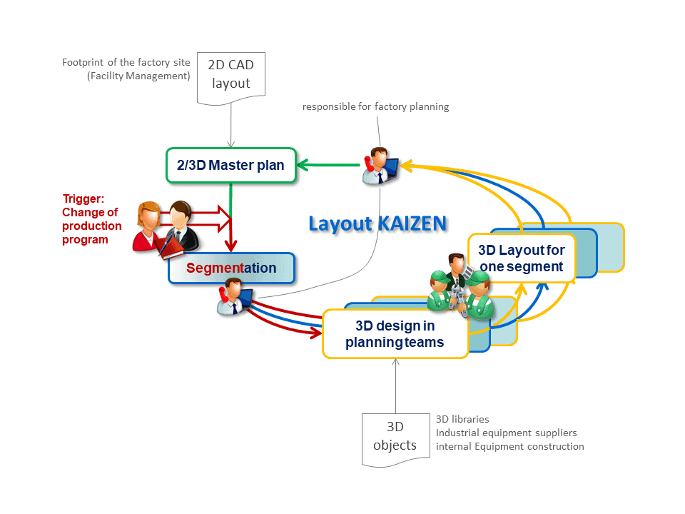
At this point, we notice the benefits of a master layout as described in step 1. The block structure facilitates a segment-by-segment approach. In other words: In each KAIZEN loop, we can identify technologically related layout segments comprising one or more blocks. These segments can then be viewed in isolation and detailed in a 3D environment. Only their spatial boundaries must be left untouched.
That may pose quite a challenge in an individual case. But it is usually well worth the effort. The alternative would be to call everything into question constantly. That would produce countless variants of the overall layout, each with its own deviating details. Sooner or later, factory planning would sink into uncontrollable complexity – irrespectively of whether in 2D or 3D.
Related topics: