Rough layout and fine layout are terms often heard in factory layout planning. Usually, they are also used intuitively. Almost everyone has an idea of what they mean. The rough stands for rather imprecise or conceptual, while the fine is rather associated with sophistication, accuracy, and high detailing. And this is where the intuitive basic understanding of the subject matter ends. Do we need to know more about it?
The four perspectives on the rough and fine layout
Well, certainly it is an advantage to be able to judge the significance of these two layout forms correctly. For it is by no means the case that a rough layout is merely the “unfinished” preliminary stage of the “correct” layout. And it is even more fatal to deal with the layout only when it is presented as a fine layout in a largely comprehensible, three-dimensional form. By then it is usually too late for many ideas for improvement. Far too much work has already been done by then. Work that is based on conceptual decisions and works that, from an economic point of view, should only be done once. For this reason, in this article, we want to show four necessary perspectives on rough and fine layouts in factory planning and discuss their use.

The Level of Development
With maturity, the temporal aspect in layout planning is to be illuminated. This is also the most easily accessible. This is because new layouts are created in a process. Starting with target planning, one will work through successive phases to realize the new factory or workshop layout. In the literature, the terms
- Ideal layout,
- Rough layout,
- Fine layout
as successive degrees of maturity of a layout. For example, in the VDI 5200 procedure for factory planning, which is widely used in the DACH region, such a path is described in phases 3 and 4:
- Phase 3: Concept planning; here a rough layout is created to represent the factory concept.
- Phase 4: Detailed planning; here a fine layout is created as a basis for the preparation for realization.
Maturity phase of the rough layout according to VDI 5200
Accordingly, in phase 3 (concept planning), starting from an ideal functional scheme, an ideal layout will be initially based, which is then to be harmonized in variants with the building structure design. In the final step of this concept planning phase, the so-called real planning, a rough layout together with the preliminary building design should describe the factory concept to be realized.
Maturity phase of the fine layout according to VDI 5200
The detailed layout is classified in phase 4 (detailed planning) of this VDI guideline. It is made clear here that a detailed layout must in general already contain everything that is required for the necessary official applications for approval and the performance specifications. In concrete terms, this means, for example, that the operating equipment must be detailed to this extent,
- to derive at least specifications for their invitation to tender (so-called functional performance specifications).
- to identify legal framework conditions according to which official approvals may have to be obtained (as an example, VDI 5200 names the German Federal Immission Control Act – BImSchG).
A similar level of detail is also associated with the fine layout for other factory systems. For example, logistics, work organization, and buildings.
The Level of Detail
Somewhat more difficult to grasp than maturity is the granularity of a layout. This perspective can also be well illustrated with the terms “resolution” or “level of detail”. A good comparison is provided by scale; we have illustrated this on our factory planning topic page using the example of a world atlas.
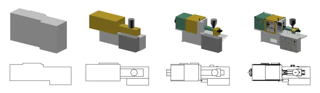
Maturity and granularity are often mistakenly equated. However, they are the proverbial two sides of the same coin. While the maturity of a layout increases with the knowledge gained about the layout objects, the granularity can always be freely selected. For example, it is possible to represent a concept for a new production site already with very detailed three-dimensional equipment models.
The danger of this is obvious: Since the concrete equipment is not yet known in detail in the concept phase, the detailed model used in the layout must be more or less wrong. Wrong in this sense means that the actual equipment later will have a different geometry in essential or insignificant parts. If a detailed model is used, nobody can recognize which parts of this model are unrealistic. Only the creator of the layout knows this. This creates a communication risk: In the minds of the viewers, a possibly false image of the maturity of the layout is created.
In modern digital planning practice, this risk is methodically countered with the concept of the so-called “Level of Detail (LoD)”. In simple terms, this means modeling several variants with different levels of geometric detail for the same planning object. These are then used depending on the maturity of the layout or layout objects. A model with a low LoD is used in the rough layout and a correspondingly higher resolution in the detailed layout.
In addition to the methodological effect, this also has a technical advantage: low-detail models generate less computing load for the hardware that has to display the layouts. This leaves more computing power available, which planning software can then use simultaneously to visualize the layout, e.g. for evaluation or optimization calculations. Alternatively, the hardware can then display more models simultaneously, making the digital planning of extensive layouts possible.
Overall, this reduces the hardware requirements for layout planning. Expensive “CAD hardware” is no longer necessary for planning tasks. This aspect should be emphasized here because in practice there is still the opinion that high-performance and cost-intensive hardware is required for digital factory planning in 3D.
The hierarchical perspective
From these preliminary considerations, especially from the granularity perspective, the need to perceive layouts as hierarchical systems arises almost inevitably. What does this mean?
- On the one hand, there is the consideration in levels. In the simplest case, the rough layout is the superordinate level and the fine layout is the subordinate level.
- On the other hand, there is the system approach. According to this, every system consists of elements, which in turn are to be understood as subsystems of the system. Here, too, in the simplest case, the rough layout can be regarded as a system of fine layouts.
The combination of these two aspects is the “trick”. It allows a view from the coarse to the fine and back in a single model. If, for example, a layout is developed in the inventory, it will be a fine layout – an image of the real situation. Logically, this can no longer be further developed in terms of maturity; it is fully developed. Regarding the granularity, it can be divided into the following illustrated levels of detail.
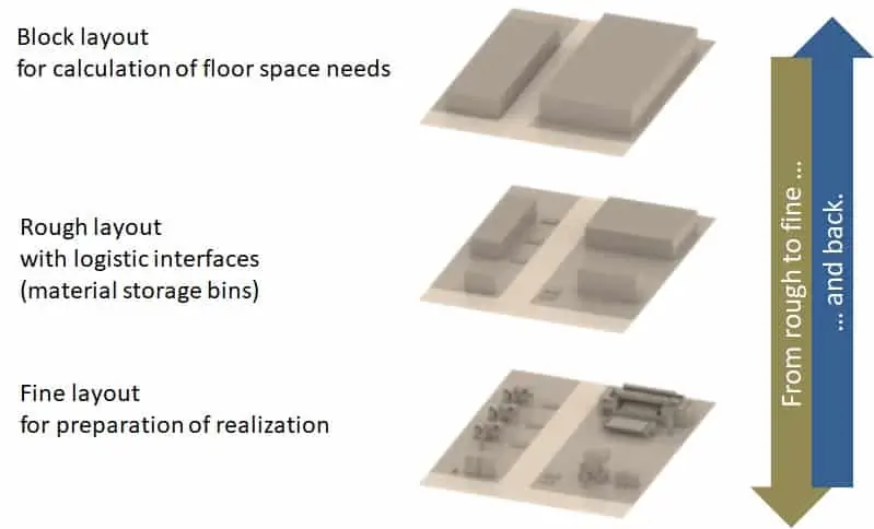
If there are questions about the factory structure, you can use the Block layout level. Moving or changing the blocks is comparatively easy while maintaining their area requirement compared to the alternative conceivable moving and fitting of the individual detailed layout objects. This alternative would be completely inappropriate about the maturity of the structure.
Example relocation with capacity expansion
Here we are talking about rather rough things, such as the general space requirements due to expected production increases. In this case, it is not simply a matter of relocating, but also of using new/different technology or automating logistics, which may become profitable. These are all things that can be roughly taken into account in the space requirements but are not yet fully developed. That is why the impact on the placement of existing equipment cannot be estimated in the level of detail of the fine layout. Moving the existing equipment to the favored area would therefore be a wasted effort in this case. In addition, the existing degrees of freedom are unnecessarily restricted and it is easy to get “lost” in the details.
The Material flow
The only problem that the previous consideration in the hierarchy perspective leaves open is the delimitation of its elements from each other. The material flow perspective offers a solution to this question.
Which planning objects of a detailed layout result in a block layout element?
The material flow forms flow systems. These are the elements that form an uninterrupted chain or network of sources and sinks. All these sources and sinks are arrangement objects in a common arrangement space. An arrangement space may only contain objects of one hierarchy level.
Illustration example
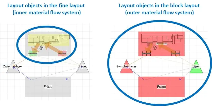
The following illustration shows an intended simple layout consisting of two hierarchy levels (block layout & fine layout). The layout objects that together form a flow system are highlighted in color in their respective hierarchy level.
- The inner flow system describes the flow of parts from the input buffer via the machine to the output buffer. This flow system is self-sufficient to the extent that it is always the same regardless of the location of the entire production station in the factory.
- The outer flow system describes the flow of containers in the factory. Warehouses and other production places are involved. This flow system is also self-sufficient, it always has the same shape regardless of the internal structure of its elements. This means, for example, that it does not matter where the input stations for turning or milling are located, the same quantity of containers must always be transported to and from the respective production station per unit of time.
Example production site
In a factory, for example, two arrangement spaces are created:
- “Location” from the block layout objects of the functional areas of the factory, i.e. e.g. incoming warehouse, outgoing warehouse, goods receipt, goods issue, prefabrication, component assembly, final assembly, and so on in a rough layout.
- “Final assembly” from the final assembly stations, which all obtain their material from the final assembly input buffers and kanban stores and provide their final products in output buffers of this area.
In this example, the input and output buffers of the final assembly are the boundary elements that form the logistical interface to the higher-level flow system “site”. All objects within the final assembly together form a self-sufficient flow system (all stations, buffers, Kanban shelves, etc., i.e. including the boundary elements), as do all objects of the superordinate flow system, i.e. the blocks of the “Location” arrangement space.
Benefits of the hierarchy for the optimization of the factory structure
The elements of flow systems can be optimally arranged to each other using factory planning methods. One speaks of ideal planning, a so-called ideal layout is created. Through hierarchy formation, both entire factories and individual production areas can be examined as arrangement spaces with these methods. This enables a holistic optimization of the factory structure with a far-reaching reduction of complexity.
Conclusion
While the intuitively accessible perspective of maturity focuses on the initial creation of a layout, i.e. the new planning (greenfield), most of the tasks of layout planning result from changes in the existing structure. Here we usually find grown fine layouts from which coarser structures have to be derived to effectively apply conceptual planning methods. You will get advantages if these structures are already included in the layout, i.e. if a hierarchical perspective has been implemented into the factory model. Only in this way can conceptual aspects of the production layout be investigated, in particular, the
- optimal arrangement of the functional areas within the production site and
- the material flow and logistics structure.
Furthermore, it is always advantageous to select a granularity for the layout objects that match the level of knowledge in planning. This is because the viewer of a layout intuitively equates the granularity with the maturity of the planning, which can easily lead to misunderstandings when communicating planning statuses.
Related topics: