In this article, I would like to take up the often-advertised issue ‘digitization by laser scanning’ for inventory survey of equipment and buildings and put it into the context of enterprise size and use cases in factory planning. This article is intended as the beginning of an article series about digitization in factory planning which will also deal with further methods.
Basic questions on the state of the art and applicability
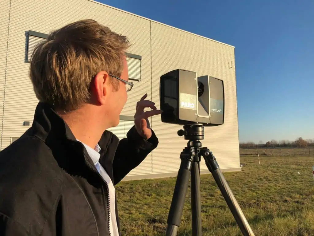
First, I would like to point out that the special topic we are now speaking about are terrestrial laser scanners – a category that is often used in planning production sites, in addition to mobile scanners. In general, it must be stated that terrestrial laser scanners from Leica or FARO erected with a tripod operate essentially more precisely in 3D measurements than mobile scanners from NavVis, for example. Instead, they are approximately ten times slower if considering the scanned area in m² per time. However, faster is not necessarily better, and the costs for scanning, in principle, already became less important. Why? This will be explained in my article.
This article is devoted rather to critical questions in the practical use of terrestrial laser scanners in factory planning. I personally have gained experience in practice and research in the field of terrestrial laser scanners since 2007 and have also been witness of the development of this technology to date. My experience, however, did not grow from the classic perspective of a surveyor, but from the point of view of a factory planner who wishes to use the collected 3D data effectively.
I am writing here also about commercially available state-of-the-art equipment. For the present, the scanners from established manufacturers do not yet use AI solutions or deep learning approaches, for example, to recognize objects directly and create in real time. You simply scan everything which turns and comes in front of your laser. Therefore, laser scanning is always mentioned in this context relatively fast when it comes to digitization of buildings and equipment. Let me tell you the following in advance:
Laser scanning is not (yet) suitable for everyone in factory planning
Viewed realistically, digitization by laser scanning is actually not effective for enterprises with a production area of less than 20,000 sq ft. If such enterprises would use laser scanning, this would be the same as taking a crack hammer to crack a nut. For enterprises of such dimensions, inventory survey by way of other means, such as fast manual measurement or supplier data with rough block layouts, is often fully sufficient. Even a 3D model can already be redundant if single-story buildings with few machines, racks and worktables in the factory hall are planned.
In the case of enterprises with an area of a few hundred or even a few thousand square meters and with lower requirements regarding accuracy, costs and utility value are currently often out of proportion. But experience has shown that even larger companies that do not fall into this category find it difficult to decide whether digitization by laser scanning makes sense. Why is that?
A planning model or digital twin takes more than a scan
If digitization by laser scanning is referred to the pure process of inventory survey, it initially only means labor and is also linked with costs for purchasing or renting hardware and software, beside the time required for the personnel. In the current state of the art, it is no problem to scan 20,000 … 40,000 sq ft in a factory per day on average when using a terrestrial scanner, such as Leica RTC 360. This is much faster than a few years ago when it was only 5,000 to 10,000 sq ft.
If I have a 3D point cloud, I can view it directly with the appropriate software such as FARO Scene or Leica Cyclone, which is provided by the manufacturer. The utility value for layout planning at this point is, however, from my point of view still relatively low. The initially raised question is deliberately provoking because the manufacturers of laser scanning devices often advertise with such applications for factory planning. Let’s have a look behind the data of a laser scanner from the practical point of view.
Point clouds as a result of digitization by laser scanning
State-of-the-art terrestrial laser scanners can measure over a distance of about 300 ft and record, believe it or not, up to 2 million points per second. In addition to the position of the point in the space, an RGB color value is stored. It is often easier for us to identify objects in colored point clouds thanks to the closeness to reality. Grayscale scans can under certain circumstances provide a clearer contrast image for reconstruction purposes. Whether a point is recorded more or less precisely also depends on the distance of the laser from the exit (nodal point) to the appropriate surface. The manufacturers often specify this as the distance deviation. Today it is approximately +/-0.04 inches over a distance of 30 ft.
But this is only half the story. The most decisive factor is the 3D point accuracy (deviation in all three axes), and it amounts to approx. 0.08 inches over a distance of 30 ft for the Leica RTC 360, for example. Then it further increases. By the way: This concerns all manufacturers. Each point within the scan will then have a fixed position in the coordinate system of the current scan and many, many millions points can be stored in a file or scan. Thus, more than 100 million measuring points can result in a minute of scanning at the aforementioned rate.
Recognize equipment in point clouds
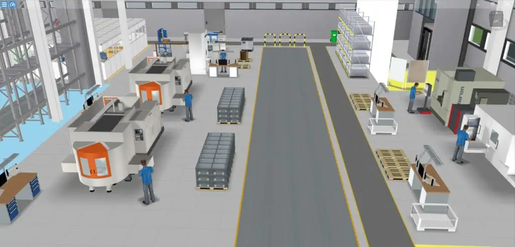
The cloud consisting of points representing a factory hall or production area, for example, can be viewed in the viewer and you can identify the objects immediately. The inaccuracy increasing with the distance can be noticed by way of a kind of corrugation or ripple on actually smooth surfaces. The scans become effectively more blurred. Depending on the resolution and distance of the viewer, the visual quality in the viewer varies, also depending on the current distance between the points. The latter becomes greater and greater in the point cloud with increasing distance. In practice, this means that the scanner will map objects that are far away only with significantly lesser points.
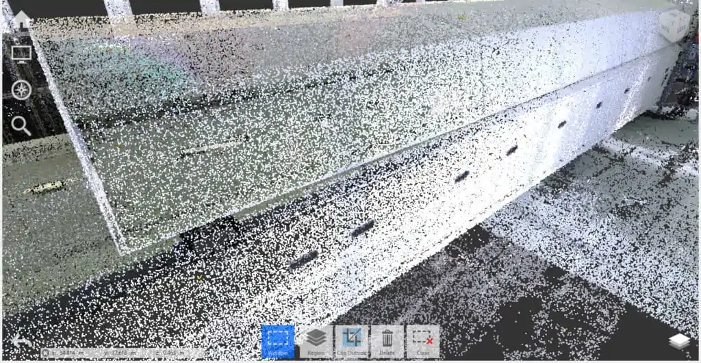
Let’s take a 2 inches wide bollard scanned from a distance of 60 ft. It is then possible that only two points can be seen due to a distance between the points of 1 inch and the object is no longer visible in the viewer. Consequently, I must come closer to be able to bring the laser beams spreading apart and emitted by the scanner closer together again. May be, then I will have 10 points with a point spacing of 1.6 inches in the horizontal, and I will already be able to identify the profile of the bollard.
You can imagine the point cloud as fine mist without lines and areas. Fortunately, our brain quickly composes an image from a colored cloud of points; the only prerequisite is that the point cloud is tight enough (s. figure above). In practice, this often means several hundred scans and many gigabytes of data in order to be able to acquire a factory.
The way to the factory layout
You probably already now notice that a point cloud is initially a quite disordered data cluster. It does not matter for the point cloud whether we want to view only a single machine, a reservoir or a wall element. Such a desired object reference does not exist although it is essential for layout planning. There is only a defined quantity of points, including (or except) all which could be recognized by the scanner in one rotation or during one scan.
A laser scanner is only as good as its operator
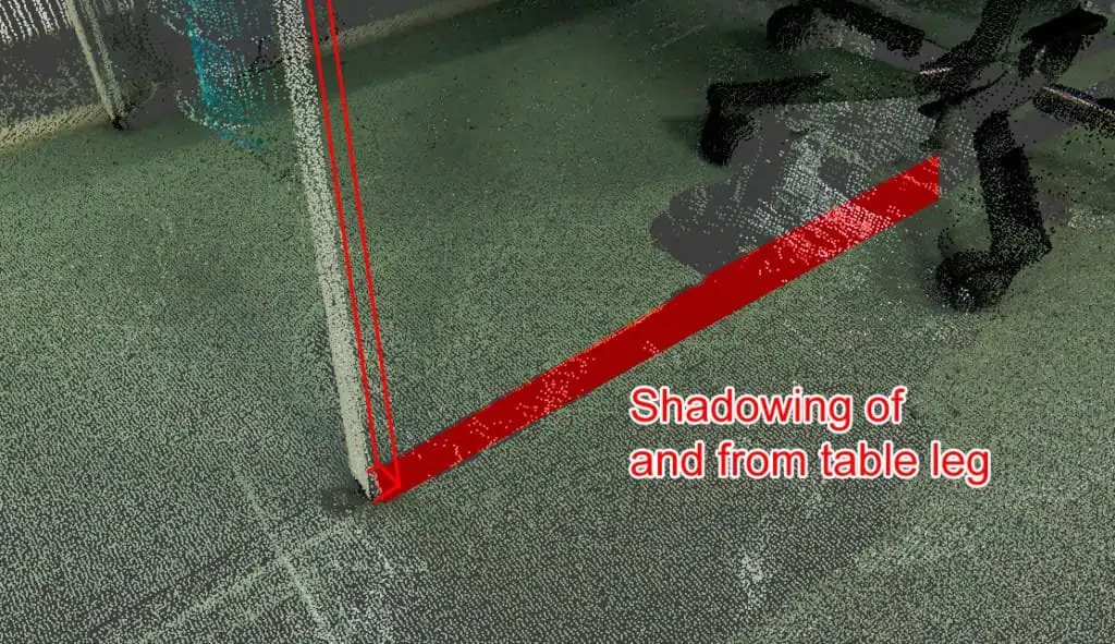
But this also means if someone parked a fork-lift truck in front of a rack, then exactly this concealed area cannot be seen in the point cloud. This can also happen during the scan while the production is running. Just as well, in turn, unnecessary objects, such as a jacket, an apple or the coffee mug of an employee on the workbench, are also scanned.
Laser scanners can neither view through an object nor filter out disturbing objects (at least currently not yet). In principle, the laser scanner only views things which are not concealed, in the same way as the human eye. And what will I do if I something do not see? I will change my position and have to install the scanner at a new position. Therefore, in the case of a high packing density (in obstructed factory areas ), I will need a lot of scanning positions so as to reach as little shadowing as possible. Nothing is more nerve-racking than to ask yourself later in the office how does the object look because data in the point cloud are missing.
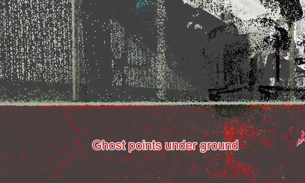
By the way: Scanners also do not like deep black or strongly reflecting surfaces. Then it often happens that holes occur or so-called phase offsets or scattering with ghost points in places where no such clouds should be.
Quick Wins through digitization by laser scanning
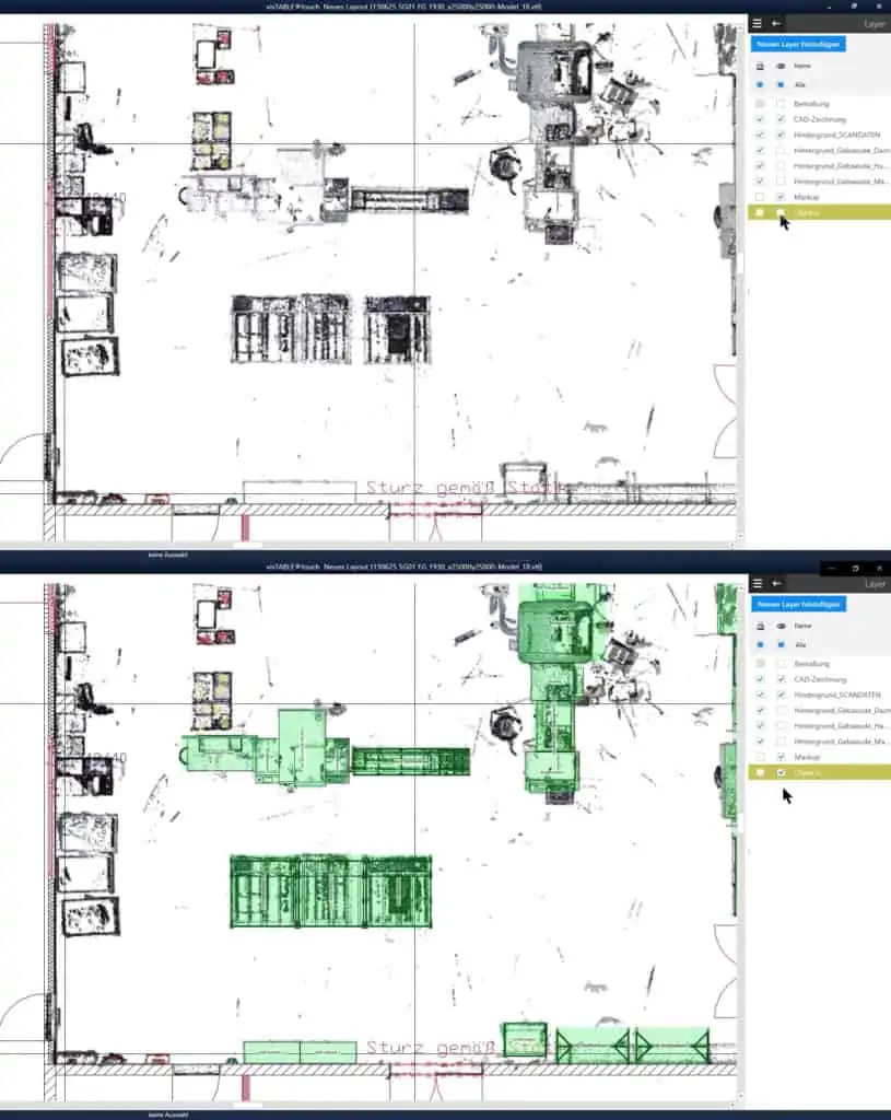
Such an unedited point cloud is often also called edge interference model. This term is also aimed at the collision check application where you load a CAD model into the point cloud and check the feasibility of the installation directly in the point cloud. Interference between a 3D surface model and the point cloud can already be recognized there very quickly. By the way: You can also measure the distances between the points by way of nearly any software for viewing point clouds.
In other words: If I have an up-to-date 3D photo of my factory, I will be able to measure distances and heights in any area acquired. The scan data need not be prepared in any special manner, and it is not necessary to dissolve the point data. But all what I need is a display software (viewer) that is specially optimized for point clouds and can handle many gigabytes of scan data and is, in addition, equipped with an appropriate host with sufficient RAM capacity.
Knowing the objective of laser scanning
To be able to make the data useable for planning, you must know the objective of their use. To this end, let’s neglect the aforementioned collision check or simple point-to-point measurement, as it is no real layout planning. In practice, this is done rather for a single system separately where any risks of collision are already to be ruled out in the phase of detailed planning. Therefore, the following typical applications for factory planning as examples:
- True-to-scale hall floor plan for the ACTUAL layout
- True-to-scale vertical section to be able to take into account building service installations at different heights
- Equipment items that can be moved for layout optimization
- Building model for adjustment with ACTUAL layout data
In all applications, I always make the decision whether I want to create 2D, 3D vector data or even only a bitmap (pixel graphic). It quickly becomes clear that the raw data (wild cluster of points) delivered from the scanner cannot be used for such cases of application. By the way: 2D reconstruction is significantly more cost-saving than 3D reconstruction, but comprises less information.
Are you still on board? Or did you decide at this point to leave us and forget this issue? We will come to useful applications – promised!
The hurdle of transformation – from points to planning objects
Let’s start from the fact that you have already assembled a complete scan from the individual scans (the so-called registration). Any disturbing points have already been removed from the point cloud (and further work steps will be ready soon). Please note that we are still always speaking about points – not polygons, not geometric primitives, and not CAD models, and we are talking about data volumes that can quickly reach sizes of many gigabytes.
Then the preparation or reconstruction for transfer into really useable data starts, which is often concealed by the providers. If you, after all, not only wish to document, but also plan your factory in 3D, something must still happen with the scan data. The second part of this article will be devoted to specific cases of application, software use cases, and practical examples. Why are the real cost drivers of inventory taking located here and are there alternatives?
Read more about it in part two of this blog article series: