In the last article on laser scanning, it was more focused on the state of the art and the result of a laser scan. The conclusion was that the actual recording of point clouds is already affordable even for smaller companies. However, the result of this process has only a small added value in the context of factory planning for the time being. This second part will therefore now focus on practical applications of laser scanning for layout planning, including a video below. What can ultimately be done with the recorded point clouds and what is required for this? For a first effort estimate, you can also download a checklist of questions about your planned project at the end of the article.
When is laser scanning used in practice?
Typical situations
- Redesign of existing factory/production
- Conversion of exhaust air
- Acquisition of machine or plant
- Relocation of machines or plants
Prerequisite for planning
- Layout data of building and equipment
Challenges
- Analog layout data in paper form or no data at all
- Digital layout often inaccurate, incomprehensible or outdated
- Data usually only available in 2D for simple area planning
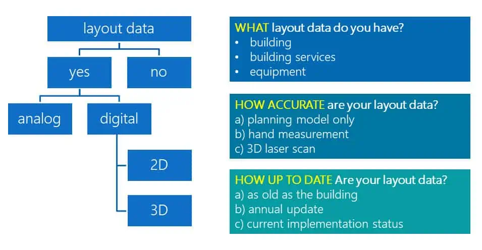
You can ask yourself the following questions in advance. The further down the structure tree you go, the better your data situation and the lower the need for laser scanning.
The simplest use case – elevation cuts
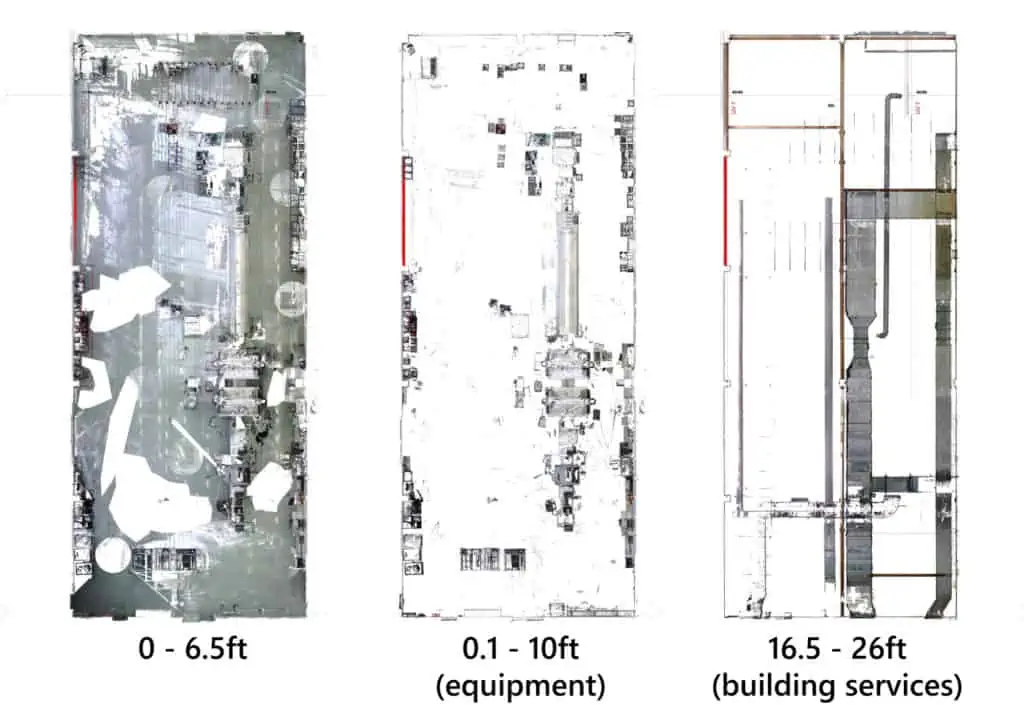
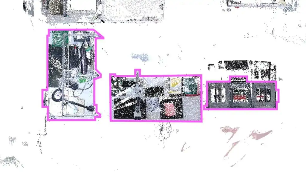
You can always create quick added value when the scan data can be used as directly as possible with little manual effort. A good example are the section graphics already mentioned in the last article. With the ReCap software, for example, you can very quickly generate hall floor plans with the visible ACTUAL layout of all equipment from a registered point cloud. Points can be easily cropped, comparable to lasso selection in Photoshop. This works well in a side view, for example, where unnecessary height segments are selected and deleted with rectangle selection. Then a graphic can be rendered from it in the top view and loaded to scale as a reference in a visTABLE®touch layout, see the following picture.
What is often concealed – Reverse Engineering in 2D and 3D
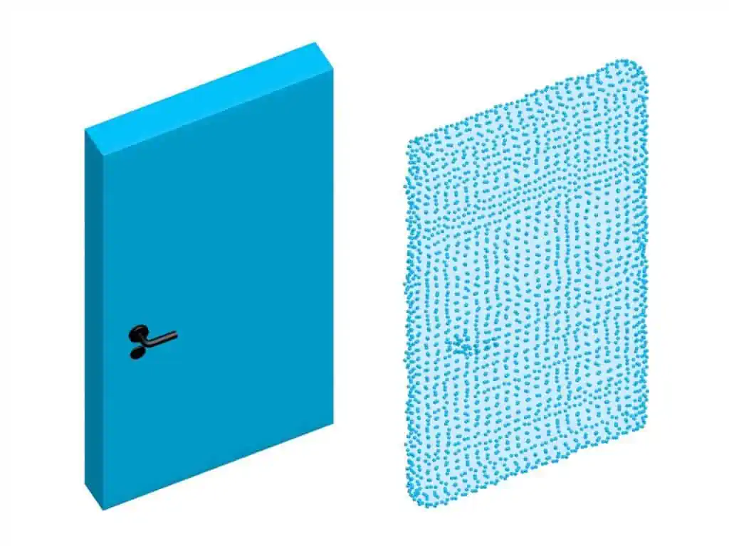
Professional service providers (engineering firms) openly discuss this issue with their customers. Avoid following false promises from hardware manufacturers in this area. Unfortunately, there are cases where disgruntled customers end up with a set of raw data from a laser scan and are at a loss. The expectation that scan data can be used directly for planning is very rarely true. After the acquisition, the work really begins. The fact is that the actual scanning takes only a fraction of the time during digitization (see graphic below). Scanners have become so fast that this step is still not negligible, but it has long since ceased to be the biggest time factor.
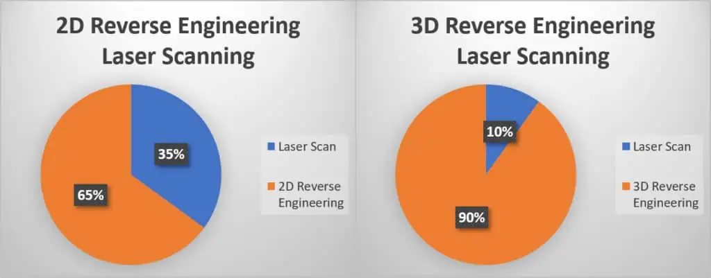
However, the generation of usable data for layout planning or reconstruction often takes up 70-95% of the total time in such projects. Be aware of this. If you scan for three days, the subsequent 3D model reconstruction can take ten times as long, i.e. 30 days. Or to put it another way, if scanning costs me perhaps 0.50 $ per 10 sq ft, the costs quickly increase to 2, 5, 10 or up to 20 $ per 10 sq ft, depending on the level of detail and the fundamental question of whether 2D or 3D. For the most part, we are talking about manual modeling work in expert software.
Why not just reverse engineer automatically with software?
Yes, there is software like EdgeWise that can fit pipelines into a point cloud with just a few mouse clicks. But even that is unfortunately not yet fully automated. This is because the problem of shading in the ceiling or TGA area (technical building equipment) often comes into play here. Pipelines in the scan can often only be seen as patches of points with holes in them. Due to shadowing during the scan from the store floor, only the lower part of the pipe (slightly more than 180° of the outer surface) can be seen. In most cases, no software can reconstruct this fully automatically.
Here, too, a CAD expert has to sit down for many hours, up to days and weeks, in order to reconstruct the piping semi-automatically. In addition, there is the usually high complexity and packing density of building services, including special structures. This can be described as a software-assisted reconstruction process that works but is still very time-consuming.
How can the dilemma of high expenses be solved?
To reduce costs significantly, the only thing to do at this point is to remove the third dimension (height) from the equation. Then, as you can see in the diagram (see graphic above left), the proportion shifts significantly towards the actual scanning.
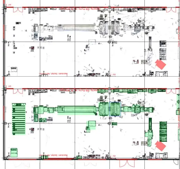
In return, this means 2D surface planning with less information content. Can you achieve your project goal with this? If so, another advantage of laser scanning for layout planning becomes apparent. You can trace 2D floor plans of buildings and equipment relatively quickly and accurately and thus create usable planning objects. In the image below you can see both manually vectorized 2D planning objects and green block models taken from a standard library in the visTABLE®touch software. Even if you only have the section graphics available in the first step, you can already start planning.
In addition, as mentioned, sectional graphics at different heights can at least help to avoid gross planning errors. Of course, this is no substitute for true 3D planning, but it may be sufficient to achieve your planning goals.
If 3D planning does become necessary, there are still the following ways to reduce costs:
- Choose a lower level of detail
- Omit areas of the factory (social rooms, TGA, outside scan for example)
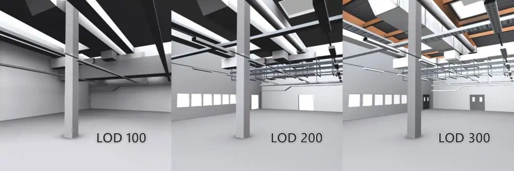
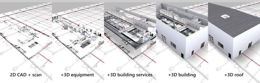
A more realistic representation can be achieved by using additional photo textures. In the following image, the modeling effort increases significantly from left to right, but so does the information content with details relevant to planning.
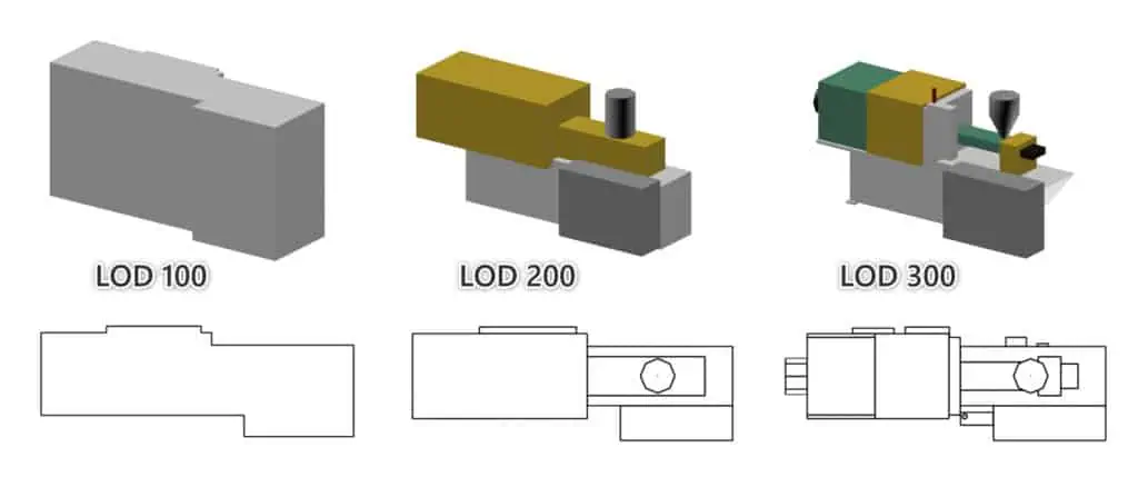
This can be similarly described in the building sector. Light openings can only be mapped with LOD 200 and higher and are often of greater importance in planning. Rough collision checks with the building services can already be carried out with LOD 100.
Complex software landscape in laser scanning
There are many tools in the form of software for point cloud processing. Only certain tools are ever needed depending on the use case. The following table is a selection that is used relatively frequently and can be described as standard software:
| Software | Developer | Selected applications | Process step |
| SCENE | FARO | clean up, registration | registration, preprocessing, export |
| Cyclone | Leica | clean up, registration | registration, preprocessing, export |
| ReCap | Autodesk | registration, crop point cloud sections, viewing, measuring, export | registration, preprocessing, export |
| AutoCAD | Autodesk | 2D derivations floor plans buildings and equipment, rendering sectional graphics | reverse engineering 2D/3D, create planning model |
| 3ds Max | Autodesk | 3D reverse engineering and generation of planning models | reverse engineering 3D, create planning model |
| Geomagic Design X | Geomagic | 3D Reverse Engineering Product Data CAD | reverse engineering 3D |
| EdgeWise | ClearEdge 3D | 3D reverse engineering of building services (especially piping) CAD | reverse engineering 3D |
| Arena4D | Veesus | viewer and editor for large mixed data of point clouds | preprocessing, export |
| PointCab Origins Pro | PointCab GmbH | fast floor plans, building sections | reverse engineering 2D/3D |
Many functionalities overlap in expert systems and each has strengths and weaknesses that need to be weighed for the particular use case. Only those who know the right mix of software and methods for their use case will be able to derive real benefit from point clouds. These process chains are then also very much tied to individual specialists or smaller teams of experts.
How does reconstruction work practically with typical factory equipment?
If the floor plans of equipment are enough for me, You can easily trace that in a CAD system like AutoCAD in a section through the point cloud. Specialty software such as PointCab, for example, has many features on board for vectorizing building floor plans. But be careful, even here you may have to consider overhanging areas at other heights that are not visible a few inches above the ground. So where do you put a section, or does it even take more than one? As you can see, even for 2D, this is not something that can be done quickly, but requires meticulous accuracy and attention by the operator and often knowledge in more than one specialized software.
Maintain outdated building drawings
What works for equipment can also be done for building floor plans. Of particular interest here is an actual-target comparison between the as-built layout and the laser scan. In this way, frequently incorrect column positions, hall walls, gates, etc. can be corrected relatively quickly, or newly created building areas can be added to the 2D drawing. As a result, you as a planner receive a valid database for the next planning project.
Do you want it to be 3D? Then you can, for example, cut a machine, assembly table or building section from the point cloud and reconstruct it in isolation in a 3D software. This software must of course support the import of point clouds. Or you can use automatic meshing in software such as Geomagic Design X or the free Meshlab. This allows data to be transferred into more compatible polygon-based formats such as Collada DAE, Wavefront OBJ or even in parametric solids.
Why not use automatically meshed planning models directly?
The resulting models are often simply too complex and often also afflicted with many representation errors. This way is tried again and again without success in practice. The result is very long loading times of factory layouts, sometimes insufficient display quality, and sluggish interaction with the 3D view due to sharp drops in the refresh rate. The higher the refresh rate, the more pleasant, faster and possibly error-free a planner can use his factory layout.
The following example illustrates this: Ideally, a rectangular surface (for example part of a machine cover) is mapped or designed with two triangles and 4 corner points. In the automatically meshed scan, however, there may then be 2000 surfaces (factor 1000) because the laser scanner has scattered many measuring points within the surface, which are automatically used for meshing.
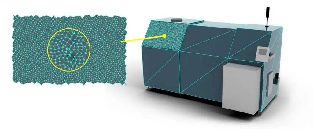
Mind you, this is then only useful for a flat surface in the entire model and not for lag-free navigation and interaction in the design. You could now use expert tools such as Geomagic Design X to search for contours in the point cloud and thus thin out the point density. Or you could then use an edge-based method to reduce the number of polygons in 3ds Max, for example. However, the result is then usually still not satisfactory. Only by remodeling with ruled geometries (rectangles, cuboids, cylinders, for example) based on the point cloud can high-quality, digital factory models be created, as the following example shows:
From points to surfaces – faster or more accurate with laser scanning?
You may have noticed that we often end up not using the original point data at all. Instead, we generate completely new data (reduced surface models) based on the point cloud. The original data then no longer flows into the factory layout.
So what’s the point of all this? In the end, it’s not so much about saving time in the as-built process. Rather, the goal is to create accurate, digital planning objects. After all, I can definitely reach my goal faster with other methods such as photo modeling (not photogrammetry) in the narrower sense or CAD data. But what Laser Scanning excels at for layout planning is producing a very accurate 3D snapshot of my factory as it was installed by contractors and technicians. The following things are then also taken into account:
- Unplanned changes/additions in the design
- Difficult to reach areas in the factory (heights, protection areas)
- Avoidance of measurement errors over long distances (up to approx. 300 ft)
In the end, the point cloud is then only a very accurate digital reference of our factory in a defined period of time. This also depends on the frequency of changes to the building and installation of the equipment. The intermediate step to manual reconstruction should be critically questioned in any case. It involves a certain residual risk of incorrect reading and modeling by a human. Automatic meshing is just as affected by this. A point cloud with many interfering points also only provides a surface model with errors. The basic principle is that what comes out is only as good as what goes in.
Scan accuracy beats speed
As mentioned earlier, terrestrial laser scanners are already quite fast, averaging 30,000 sq ft per day. However, a mobile scanner can cover up to 250,000 sq ft in the same time. For medium-sized companies, this is often more than the entire factory floor. Here you already come to a negligible cost factor. But what is often overlooked with mobile scanners is the significantly higher inaccuracy or noise in the point clouds. We are no longer talking about 0.08 or 0.2 inches point accuracy, but 0.4 inches and more at short distances. In practice, this manifests itself in very wavy surfaces, comparable to a lake over which a light breeze sweeps.
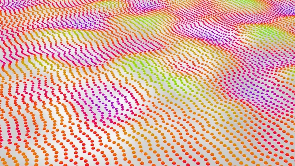
In addition, there is also a high inaccuracy of up to several inches at any edges and corners. In fact, there are no sharp edges like in reality. By the way, this is also a problem that terrestrial laser scanners have, but on a much smaller scale.
Would you use this as a data basis for construction planning?
For the concept planning of a factory, these results are theoretically good enough. But this inaccuracy (see picture above) creates very practical problems in the traceability to clean surface models. Where do I place a floor level of a building, 1 inch further up or further down? Is it a socket or just a bunch of scatter points? Averaging in the point cloud can help you often, but uncertainties remain. Especially in detailed viewing areas like complex equipment, this can quickly lead to “interesting” questions. Reference photos then have to be compared with the point cloud more and more frequently in alternation.
Experience shows that you lose a lot of time here in understanding the point cloud or simply cannot derive a sufficiently accurate model in the time available. This is where terrestrial scanners have a clear advantage. A much better defined, more accurate point cloud can save days and weeks of reconstruction work and is simply better suited for many factory design use cases. That’s why, in practice, a mix of mobile and terrestrial scanners or just the latter has been proven to be the best solution.
The fact is, and you will get this confirmed by any reputable service provider, the traceability takes place in a complex process chain, consisting of work steps that can only be performed by experts. Here, at the latest, it becomes clear why these services are relatively expensive and require larger budgets, especially for medium-sized companies.
Is laser scanning worthwhile at all?
From my experience, laser scanning can make sense for layout planning if the overall digital data situation is very poor. Or you may not be able to get any or hardly any usable CAD data from the equipment supplier and may be in the process of digital transformation starting from paper planning. Buildings have grown historically and have not been digitally maintained for decades. Heights (complex TGA, gates, different ceiling heights) in existing buildings cannot currently be taken into account in planning and have already frequently led to expensive planning errors.
In the end, it is always a matter of judgement, also depending on the production area to be planned. Is it 100,000 sq ft? Or maybe, due to the complex factory structure, it makes sense to create an exact image of your plant even at 30,000 sq ft. In summary, the following points for consideration:
- production area to be planned guideline from 30,000 sq ft, >100 employees
- very inaccurate as-built layouts, very outdated building plans, possibly only paper
- currently, only area planning in 2D, but TGA planning, relevant ceiling heights required
- frequent additional costs due to planning errors and time-consuming coordination processes
Who is proficient in laser scanning for layout planning?
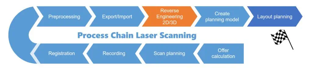
It’s best to look around for reputable service providers who have many years of experience in laser scanning. For larger projects, it’s best to choose companies that deal exclusively with this topic. The fact is, laser scanning requires experienced experts, from the calculation, planning and execution of the scanning to the customized preparation of the scan data for the target application. Behind this is a complex process chain with a wide variety of methods and tools. It can also be important that you choose a provider who has already accompanied several factory planning projects and is not only familiar with GIS and BIM but also knows the special requirements of layout planning. This is because the data basis for the smart factory is only created through reverse engineering.
It can also work in two stages as follows, if both sides work well together:
- inventory point clouds by experienced service provider in the field of laser scanning.
- conversion into usable data, for example by a specialized software provider in factory planning who knows exactly what is required
plavis GmbH also provides support for inventory recording
Finally, I would like to briefly explain this to you using our example as well. As a software provider, we also offer customers laser scanning for layout planning with visTABLE® from a single source in Germany. This has the advantage that we know exactly how 2D and 3D data must be structured so that they work optimally with our software for layout planning. For larger, even international projects, we are also happy to refer you to specialized service providers. This may also involve further requirements, such as construction planning (BIM), documentation or additional measurement data (temperature, for example). In the end, our customers should achieve their set goal, regardless of the method.
plavis GmbH supports you with advisory support
Through many years of experience in our own laser scanning projects combined with our visTABLE® software, we have come to understand the advantages and disadvantages of this method of capturing existing conditions for factory planning. We are able to pass this knowledge on to you. We know exactly how 2D and 3D data must be structured to work optimally with our layout planning software.
For larger projects, including international ones, we are also happy to refer you to specialized service providers. This may include additional requirements such as construction planning (BIM), documentation, or further measurement data (e.g., temperature).
In the end, our goal is for our customers to achieve their objectives—regardless of the method used.
Checklist to determine the effort?
It may well be that the composite point cloud model alone will help you in a 3D viewer. Maybe just for quality management, to identify cluttered corners or trip hazards in your factory. But if you want to go further in the direction of reconstructing planning objects for digital layout planning, the following cost drivers should always be considered:
- How large is the area?
- Do multiple floors need to be scanned?
- 2D or 3D?
- Which level of detail, also called LOD, is required?
- What is the complexity or packing density of the scan area?
- What can be omitted?
It is best to discuss these requirements in detail with your service provider. What is really necessary and what can be dispensed with for the intended planning goal?
Alternatives to laser scanning
- verified and optimized CAD product data from equipment supplier or architect
- 3D photo modeling of simply structured equipment
- use of an integrated software library with type representatives and block models
- verified and optimized 3D models from online portals as a source for similar design models
Final conclusion on laser scanning for layout planning
I hope that I have been able to give you an understanding of laser scanning from a practical point of view and provide you with some valuable tips. To answer the question already asked in the first article. Yes, digitizing using laser scanning can be useful. It inherently has a useful documentation function built-in because it creates a very accurate 3D snapshot of the factory. It is definitely one option of many on the way to a digital factory model, but it is also not a magic bullet. The technology still has a lot of potential for further development and will become even more attractive for smaller companies in the future.
The resulting application possibilities are diverse, but also often associated with high costs. Perhaps it is also a mix of different data sources and methods that leads to the digital factory model. Successful companies have always achieved this step by step over a longer period of time. Soon, more possibilities for digitalization will be presented here on the blog. In any case, it’s worth knowing the alternatives to make the digital factory model a reality step by step.