A modern industrial layout is no longer defined solely by machines and production lines. It is shaped by a wide range of technical installations operating behind the scenes to ensure smooth processes – including custom-designed steel structures. Whether as supports for conveyor systems, overhead bridges for utility lines, or access platforms for maintenance, these steel elements are often invisible yet critical pillars of a functioning factory.
But how should such structures be integrated into the planning process? Does a factory planner need to be a structural engineer or steel construction expert today? The clear answer: no. Designing an industrial layout is an interdisciplinary task, requiring close collaboration between different fields of expertise. What matters most is understanding the applications and possibilities of these structures – and knowing when and how to incorporate them into the planning process.
This article outlines the role of steel construction within an industrial layout, highlights common components and beam types, and explains how a structured planning approach – from concept to implementation – leads to success. Most importantly, in the final section, you’ll learn how factory planning with integrated steel structures can succeed, even without in-depth structural engineering knowledge.
The Role of Steel Construction in Factory Planning and Areas of Application
Factory planning encompasses more than just arranging machines and organizing material flow.
An efficient industrial layout also considers the structural elements that technically support operations. Increasingly, this includes integrated steel structures that are embedded into production and logistics areas as functional components. These constructions make use of vertical space, guide utility systems, and provide access to technical installations.
Typical applications of steel structures within the layout include:
Conveyor systems
Load-bearing frameworks for roller conveyors, overhead monorails, or chain conveyors – for example, to bridge gaps between assembly lines or to connect production to logistics areas.

Media infrastructure
Steel frames or bridges used to support cable trays, compressed air lines, or sprinkler systems. These installations reduce floor congestion and improve maintainability.

Maintenance platforms and working decks
Used for inspection and servicing of machines, aggregates, or utilities. In many factories, such steel platforms are a recurring feature of service zones.

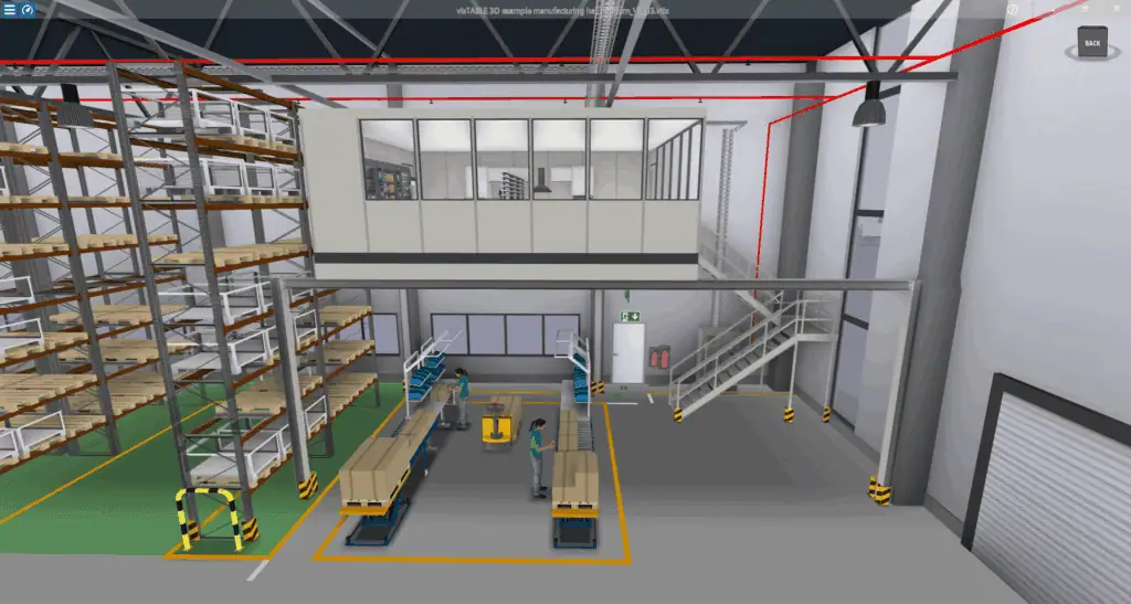
Storage platforms and intermediate levels
Enhance space efficiency in high-ceilinged facilities – for example, to store materials, support small parts picking, or accommodate technical equipment. Even offices or social areas, such as team leader workstations, can be integrated on these platforms.
Beyond the spatial benefits, these steel elements also provide organizational advantages: they support a clear separation of functions within the layout, reduce disruptions in the production flow, and maximize the use of available height – a key factor when space is limited and cost pressure is high.
To be effective, however, these elements must be considered early in the planning process.
The placement of beams, columns, or platforms can significantly impact routing, ergonomics,
and safety concepts. That’s why it is helpful to model steel components as 3D objects during layout development and evaluate them in relation to process and technology. The final section of this article explains how this works in detail.
Overview of Steel Beam Types
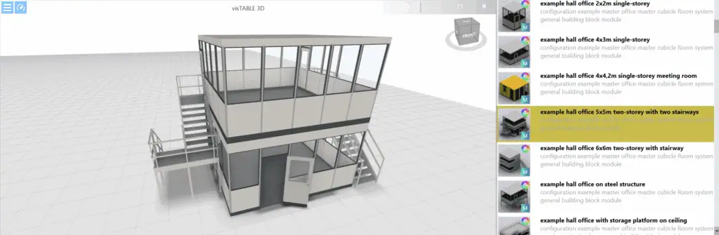
Although factory planners are generally not responsible for the structural design or detailed specification of steel constructions, a basic understanding of common beam types is still useful – especially during the conceptual phase of industrial layout development. In modern factory planning tools such as visTABLE®, many steel components are available as objects and can be placed directly within the layout.

Knowing the different profile types enables planners to design more effectively, visualize more realistically and communicate more clearly with structural specialists.
Here are some of the most commonly used steel profiles in practice:
- IPE beams (European I-section)
Slim and versatile, suitable for light to medium loads. Ideal for platforms, walkways,
or support structures beneath conveyors. - IPN beams
The classical I-section with tapered flanges. Still used for basic construction tasks, although increasingly replaced by IPE profiles. - UPE beams
U-shaped with parallel flanges, preferred for edge beams, frame constructions, or as cable tray supports. - HEA beams
Wide flanges with reduced weight make them suitable for media bridges or lightweight secondary structures. - HEB beams
A heavier version of the HEA beam, used wherever high point loads occur – e.g., beneath heavy machinery or conveyor systems. - HEM beams
The most massive profile in the HE series, designed for very high loads and large spans, such as those found in multilevel platforms or heavily loaded crane beams. Rare in typical layouts, but useful for key structural applications. - Special profiles
These include cold-formed C- and Z-sections (for lightweight secondary structures), as well as hollow steel tubes (round or square) for custom or architectural applications.
Overview Table – Steel Beam Types in Factory Planning
Beam Type
Profile Shape
Characteristics
Typical Applications

IPE
Slim I-section
Lightweight, versatile, cost-effective
Platforms, walkways, light conveyor structures

IPN
I-section with tapered flanges
Traditional, increasingly replaced by IPE
Basic frames, low static requirements

UPE
U-section with parallel flanges
Cost-efficient for boundary/guide structures
Cable trays, media routes, edge frames

HEA
Wide flange, lightweight
High capacity at low weight
Intermediate levels, media bridges, secondary beams

HEB
Heavier HE profile
Greater load capacity than HEA
Main load-bearing beams under heavy equipment

HEM
Massive HE-profiles
For extreme loads and long spaces
Heavy-duty platforms, crane structures
C-/Z-profiles
Cold-formed, thin-walled
Lightweight, easy to install
Lightweight framing, cladding, secondary components
Round/square tubes
Closed hollow profiles
Torsion-resistant, visually appealing
Custom designs, guardrails, exposed design structures
A qualified structural engineer handles the exact selection and structural design of these profiles.
For the factory planner, it is sufficient to define rough requirements regarding load capacity, location, and intended use – for example, within a functional specification or layout concept.
The next section explains how this conceptual planning step is structured and how it fits into the overall process of designing steel structures within a factory layout.
Approach to Planning Steel Structures Within Factories
Planning steel structures within an industrial layout requires a structured and methodical approach. While the factory planner does not need to be an expert in structural engineering or steel design, it is essential that they can identify, document, and communicate functional requirements and integrate them systematically into the planning process.
A proven method for this is the phased planning model described in VDI 5200. This model divides factory planning into distinct stages – from defining objectives to realization – and follows an iterative process. This means that the layout is developed in multiple planning loops: beginning with the core processes (e.g., manufacturing and assembly), followed by supporting processes (e.g., transport, storage), and finally by peripheral structures, such as steel components for conveyors or storage platforms.
1. Defining Objectives
At the beginning, the overall planning objective is clearly defined:
What needs to be changed or created?
What are the spatial, functional, and process-related requirements?
2. Basic Data Collection
This phase gathers all relevant information to support future decisions – including process data, space requirements, building conditions, existing equipment layouts, and utility connections.
3. Concept Development – Focus on Steel Construction
This is the core phase of layout planning, and where steel structure planning begins to take shape. It includes four key steps:
3.1 Structural Planning
This step locates the core and supporting processes within the layout. Here, functional requirements for steel structures emerge:
- Where are support frames needed for conveyor systems?
- Where might elevated storage platforms make sense?
- Which areas require structured media routing?
3.2 Functional Sizing
Based on those requirements, the type and scope of steel construction are defined in broad terms – such as length, span, or position of structural elements. At this point, the focus is not on exact measurements or load calculations, but rather on space requirements and functional roles.

3.3 Ideal Planning and 3.4 Realistic Planning
In these steps, multiple layout variants are developed and evaluated based on real-world constraints – including existing buildings, material flows, and safety zones. The goal is to align steel structures with process flows:
Where should columns be placed to avoid interference?
How much space is needed for platforms or media routes?
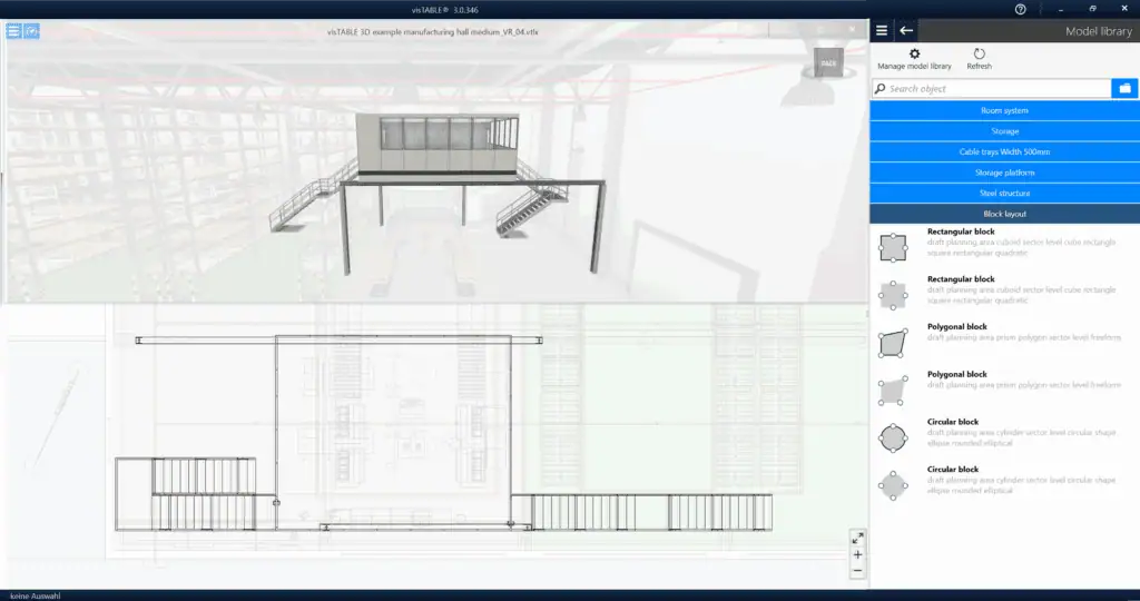
A planning software like visTABLE® typically supports this phase, allowing users to model steel elements as placeholders or “building zones.”
The resulting layouts remain at the conceptual level—they are not detailed construction drawings but rather serve as a spatial and functional guide.
📌 Important: No static calculations are performed at this stage. Planning is based on functional logic and feasibility within the bounds of physical plausibility.
4. Functional Specification for Tendering
A key feature of this approach is that the factory planner does not perform the detailed steel design. Instead, a functional specification is created based on the conceptual layout – before the detail design and permit application steps (as defined in VDI 5200, sections 4.1 and 4.2).
This functional specification (cf. VDI 5200, section 4.3) typically includes:
- the purpose and functional requirements of the steel structure,
- the required spatial geometry (e.g., modeled in visTABLE®),
- preferred column positions and designated free zones for production.
5. Preparation for Realization
During the supplier selection phase (cf. VDI 5200, step 5.1), the following tasks take place:
- 5.1.1 Request for proposals (RFP)
- 5.1.2 Contract award to the selected supplier
5.1.3 Monitoring of Detailed Design
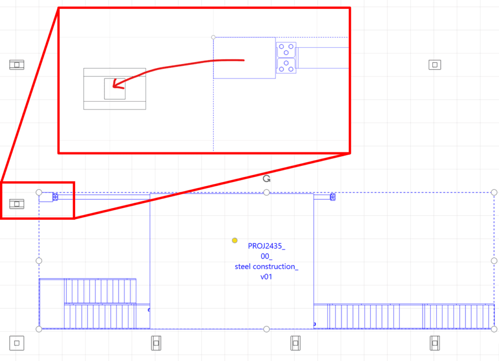
Once the contract has been awarded, the steel construction supplier delivers a detailed design, typically in the form of a CAD or 3D model. This model can be imported into the layout planning software – such as visTABLE® – to be compared with the conceptual layout developed earlier.

To ensure proper alignment, a common reference point is defined – usually a specific column – which serves as the insertion anchor in the layout.
The factory planner then checks:
- whether all functional requirements have been fulfilled,
- and whether there are collisions with processes, pathways, or existing equipment.
This coordination is carried out in close collaboration with the supplier and may require several iterations – especially if modifications are needed or the construction design evolves during development.
Final Step: Integration into the As-Built Layout After the detailed design has been approved, implementation planning proceeds (cf. VDI 5200, section 5.2), followed by on-site construction and supervision (cf. VDI 5200, section 6: realization monitoring).
Upon completion, the finalized steel structure is fully integrated into the factory’s as-built layout – serving as a documented and validated part of the long-term factory structure.
Related topics: