Have you ever read about or tried how 3D models can be automatically generated from photos? Photos have become a mass commodity through smartphones, created in all kinds of life situations. Couldn’t you then very easily capture equipment in a factory in 3D in this way? And what is the difference between photogrammetry and photo modeling anyway?
What is photogrammetry?
Photogrammetry means non-contact measurement and evaluation to determine the shape and position of an object. In simpler terms, I take a photo and create a digital 3D model of my chosen subject from my images. The process for an automatic backtrace then usually looks like this:
- taking seamless series of photos around a target object.
- transfer and setup of the photo series in a photogrammetry software
- automatic reconstruction of a 3D model (points, surfaces)
- cropping to relevant object area
- optimization or remodeling based on the generated 3D reference
What do I have to consider with photogrammetry?
At first glance it seems quite straightforward and simple, but it turns out to be practically difficult in factory planning already at step 1. Because with an automatic backtracking via image analysis, the photos are the all determining factor for the result. The following are possible sources of error:
- Excessive changes in perspective of predecessor/successor in a photo series
- Variable exposure of a camera
- Blur due to poor focus or camera shake
- Low-light lens leads to image noise
- Interrupted series of images due to poor individual shots
- Partial obscuring of the subject by moving objects or obstacles
- Too reflective surfaces, not viewing angle stable
- Too high packing density in the factory, no possibility to crop target object
LiDAR (light detection and ranging) in comparison, which terrestrial laser scanners also use, enables precise point measurements with distances between sensor and target object. Photos or pixel images do not provide this information.
Practice meets photogrammetry
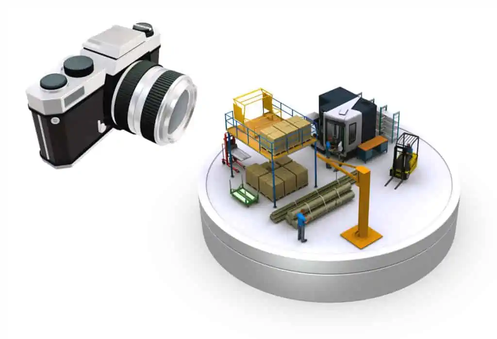
Especially in a factory it is not so easy to create a good data base for photogrammetry. Do you know the examples where a small porcelain figure is standing on an electrically driven turntable? For this purpose, a professional camera is perfectly aligned to the motif under studio conditions with automatic serial exposure. The software loves this data basis. Hardly any shadowing, a seamless photo series in very small angular steps around the motif, constant exposure and high image sharpness, see the following picture:

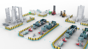
Unfortunately, this does not correspond to the practice in factory planning. There it can be difficult to keep a larger plant of three or more meters height always in the field of view of the camera. Columns and other objects may block the view or the packing density is simply too high to keep the minimum distance to the target object. If an employee even runs in front of your camera or parks a forklift in front of your subject, you can start the current photo series from the beginning.
Photogrammetry requires precise photo series taken according to defined rules. The more accurate and error-free the measurement is, the better the evaluation will be later on. Once you have somehow mastered this step, you transfer the image series to the software. In short, you usually set up several photo series for one and the same object. Depending on the software manufacturer, special software functions support you here in order to achieve the optimum result. Expect to spend a lot of time. The more complex your object is and the more individual series of photos have to be linked, the more time-consuming this step will be. After that, the actual calculation of the 3D model can take place. Depending on the provider, this job can also be outsourced to the cloud.
What software is available for evaluating photos?
The following is a selection of software for photogrammetry:
Except for Meshroom, all products are fee-based and require expert knowledge to use effectively. Some products also support LiDAR data processing.
Calculation of the 3D model in photogrammetry
Only after this step you will finally know if your input data was good enough for a regression into a 3D model. At this point, the calculation may be aborted or the generated 3D models may simply not meet your expectations. This is especially annoying if you have no possibility to repeat the recordings. However, we assume that you also succeeded in this step. Below you can see an example, which was converted from 140 photos with the software Meshroom into a 3D model.
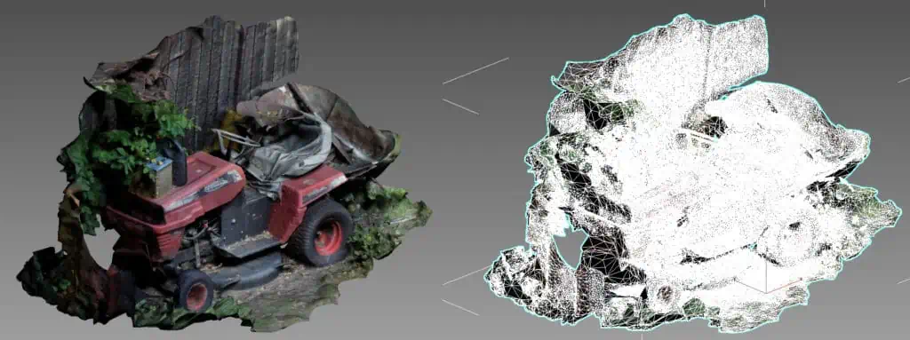
The result is then either a complex point cloud or an already meshed and colored surface model. However, don’t expect your equipment to now be neatly separated as a planning model. The example in the picture above shows this very well. Similar to laser scanning, objects are also digitized that you actually did not want to have. This can be anything that the software has detected in the photos. This often includes ground surfaces in the immediate vicinity, containers, outgoing pipelines or objects in the background. Likewise, of course, shadowing occurs because areas were simply not visible in the photos. The idealized vase on the turntable does not know these problems.
3D model yes, but practically usable?
So you don’t get a planning object, but rather a holey, blurred section of your factory. In a subsequent step, this must first be converted into usable data. What this means in practice can also be read in the blog article on laser scanning. By the way, despite lower accuracy, the amount of data can be similar to a 3D scan with a terrestrial laser scanner. The lawn mower example above includes half a million faces and maps only one side of the machine. The amount of data is about 100 times higher than desired. Direct use of the generated 3D models in layout planning is not recommended for this reason alone.
Does photogrammetry then make any sense at all?
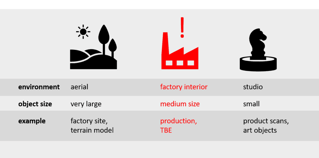
Pure photogrammetry is rather unsuitable for the object area factory because already the measurement is afflicted with numerous uncertainties. Unfortunately, the requirements for the input data, i.e. photos, are too high to work in practice. Two major fields of application have emerged for photogrammetry. On the one hand the aerial measurement by the use of drones, also called UAV (unmanned aerial vehicles) and other aircraft, and on the other hand in the close-up range on turntables and under studio conditions. The object area factory lies quasi in between.
Laser scanning is clearly superior here in the comparison, since the position of a point in the space already takes place during the actual measurement. Therefore, photogrammetry and LiDAR are also combined in practice in order to use the advantages of both methods. Some examples of this, which even already reach the consumer sector, follow below. As a result, the acquisition process is much safer and more accurate, and thus the data quality is also better. But with both methods there remains the high effort of reconstruction or transfer into really usable planning models. Could photo modeling be a useful alternative here?
How does photo modeling work?
Photo modeling is to be seen more as a rough reference modeling than algorithmically controlled reconstruction process. The data basis is also photographs as in photogrammetry, as the name suggests. However, a) much fewer photographs are needed and b) they are enriched by dimensional information. The photos also do not have to be taken exactly as a circulating photo series, but rather serve here as a loose reference for a manual reconstruction process. Basically, the better the photos, the better the result. The procedure is as follows:
- taking some relevant photos around the target object
- measurement and registration of relevant main and secondary dimensions in photos
- 3D modeling based on photo references
Less work steps than photogrammetry
In contrast to photogrammetry, there are only three work steps. However, the decisive difference here is that a CAD or modeling expert models the object with the help of the photo references. There is no automatic regression of the 3D model. In principle, this also eliminates the strict requirements for input data compared to photogrammetry. For example, if the door of a machine’s workspace is obscured in a photograph, it can be reconstructed using a second, better photograph. Likewise, the modeler is not bothered if a blurred photo slips in or the exposure was different.
What can lead to abortion in photogrammetry, a human being compensates by his experience and intelligence. In principle, almost any 3D software can be used for modeling. However, if you also want to use photos for realistic texturing of your models, it is best to use so-called DCC systems (digital content creation). Typical software from this category include Blender, Cinema 4D or 3ds Max. These also allow the 1:1 export of this information to 3D viewers, VR systems or even planning software such as visTABLE®touch.
How do the dimensions get into the photos?
These are often created by hand-measuring an item of equipment in the inventory. This can be done with a tape measure or handheld laser measuring device. Usually only some main and secondary dimensions are needed as shown in the following picture.
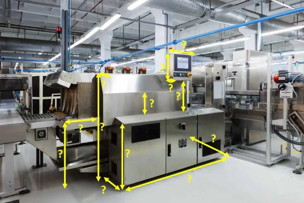
It is important to have an exact picture of the installation area for the factory planning. You can see that the modeler has to rely on the dimensions. If a dimension is measured incorrectly or entered incorrectly, this can lead to planning errors. Often, however, an error is already noticed during the reconstruction process and can thus still be corrected.
What are the advantages of photo modeling?
The principle is much closer to the rather chaotic situation in practice in a factory. The method has much lower requirements on the input data, which means photos in comparison to photogrammetry. It is therefore possible to reconstruct a 3D model even if there is no perfect data basis. Photographs can be taken by practically anyone since far fewer rules have to be observed. This makes it possible for a service provider to outsource steps 1 and 2 to the customer after coordination.
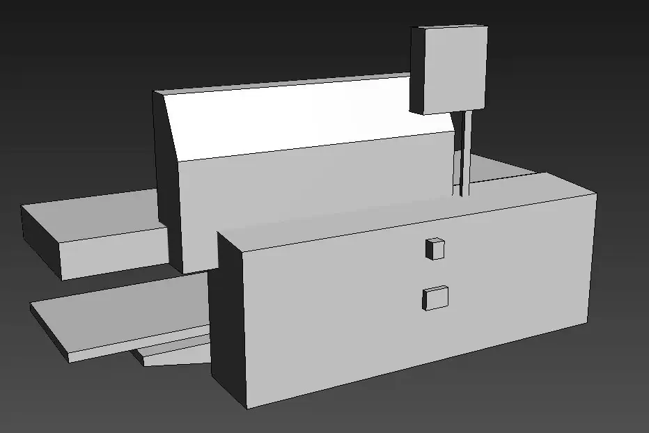
Another advantage is the targeted modeling with rule geometries in a CAD system. Only the areas that belong to the planning object are modeled in the desired or possible resolution. The result is a highly optimized planning object. Provided that the dimensions in the photos were correct and the modeler did not make any errors during the traceability, you will receive a planning object with the correct footprint and height.
If desired, the photo references can also be used for texturing the raw models. This then leads to very realistic 3D models, despite a very small amount of data. Summarized again the following advantages:
- Only targeted reconstruction of desired object areas
- Very lean, simplified planning models with low data volume
- Realistic visualization possible
- No experts required for data provision
That sounds promising at first, but what are the disadvantages of this method?
What are the limitations of photo modeling?
As already mentioned, errors can occur during manual surveying, when entering the dimensions in photos, or even during tracing, which then lead to inaccurate planning objects. Likewise, planning objects are only as accurate as the dimensions are. Areas or objects that are not dimensioned are then modeled approximately on the basis of the photos. This is fine as long as they do not affect the design of the footprint.
Furthermore, due to the limited amount of dimensional data, the level of detail of the reconstructed 3D models is usually lower than with laser scanning or the reduction of CAD product data. You can also see that as an advantage, as it means that even a larger 3D layout can be displayed without delay. Photo modeling is not applicable or only with difficulty for complex and open structures. In this case, you either need a lot of dimensional information or there are a lot of uncertainties that would make modeling very delayed or error-prone. This method also usually always requires local accessibility for manual surveying. Thus, you cannot model TBE with this method, but usually only equipment directly on the store floor. The disadvantages are summarized again:
- Possible errors due to manual measurement, dimension entry in photos and manual reconstruction
- only useful for planning models of low complexity
- only measurable objects possible
Can photo modeling replace laser scanning?
Clearly no, but it can be a useful alternative or supplement to the digitization of simply structured equipment. Especially cabinets, containers, tables or simple designed machines are often cheaper to reconstruct with this method. For high complexity, very large object dimensions and hard to reach objects, especially buildings and complex production facilities, laser scanning remains the method of choice or alternatively the processing of CAD data from architect and equipment supplier.
Hybrid solutions of photogrammetry, photo modeling and LiDAR
In addition to largely automatic or manual tracing based on photos alone, there are also hybrid forms. For example, in the PhotoModeler software, you can also reconstruct 3D objects by linking manually set markers in several photos. This semi-automatically generates directly usable planning models. In this way, the software can recognize the allocation of 3D surfaces by the user input made. However, this only works as long as you have captured the object from all sides without interference and have also set the markers correctly. The ideal case is simple cuboid objects with exclusively planar surfaces with precisely defined object boundaries, i.e. corners. At least one reference dimension is also necessary so that the software can scale the model correctly.
Also interesting is a hardware-based approach of the company Clauss with the scanner RODEONmetric Basic where photo and targeted point measurements can be directly transferred into simple 3D surface models.
However, as soon as objects become more complex, the effort required to return them to 3D models using these methods also increases dramatically or simply becomes uneconomical. In addition, expert knowledge is also required for the referencing of markers or the modeling of surfaces. The resulting accuracy depends on the user and can sometimes even be lower than with manual photo modeling.
Area-wide use of LiDAR
Photos and LiDAR are in principle also combined in terrestrial laser scanning and already applied in factory planning. In outdoor areas, for example, drones are used at heights of approx. 10-50m, which take distance measurements via LiDAR in addition to taking photos. The combination of both information immediately produces accurate 3D point clouds that derive their color values from high-resolution photos. Drones are also sometimes used indoors. However, this usually only works when production is at rest, if only for safety reasons. Shade-free images are also only possible with low packing density and objects with as simple a structure as possible.
Another interesting feature worth mentioning is the LiDAR scanner installed in iPhone 12 Pro and iPad Pro models and above, which captures 3D points up to a distance of approx. 5 meters. This can be tested very easily with the free 3d Scanner App™. To do this, simply move around the target object with the smartphone until all sides have been captured. You can export and further process the created 3D model created as Wavefront OBJ, Collada DAE or Stereolithography STL, for example. Apple plans to install LiDAR sensors as standard starting with the iPhone 13.