Blog
What you should definitely know about Factory Layout Planning
Learn what is important when optimizing your factory. The factory model is the key to designing, evaluating and communicating solutions properly — from the first draft to implementation.
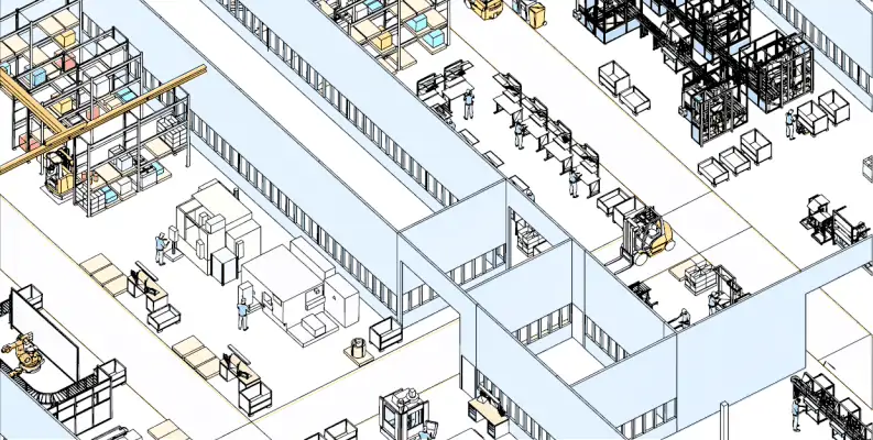
What is layout planning?
The term layout planning is composed of two terms with the following meaning
- Layout: to lay out, plan or draft, is also to be understood as a detailed visualization of a mental picture for the later execution
- Planning: the mental anticipation of actions in consideration or comparison of possible variants
Both terms imply the design desire of a future state.
When planning equipment and machinery in a factory layout, it is always of prime importance to minimize internal transport and to keep the costs always as low as possible. There are many layout objects in a factory, such as machines, worktables or warehousing elements, from which transports can be started.
Therefore, an optimum arrangement in a layout is also a challenge for the planner since he must easily include hundreds of different transport relations in an overall view. This will then be subject of material flow planning. In addition to the transports, the area required for equipment and material is an important factor in layout planning, as it decisively influences the costs of premises.
Why it matters?
Layout planning is part of factory planning and often has a medium to long-term time horizon, in contrast to factory operation which is frequently based on day-to-day considerations and possesses a steering function. The procedure there also differs from that in layout planning.
What is the right way to go?
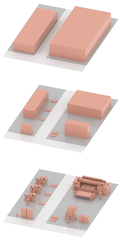
The layout of a factory is planned in hierarchic levels (see diagram on the right) to reduce the complexity of planning to a reasonable degree. This results in reduced time for planning; furthermore, better solutions can be achieved in the same time. The level of detail in layout planning increases with each narrowing of the perspective – from the production location (gray) via the factory hall (blue) to the machining group (green).
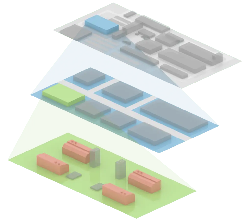
The focus switches repeatedly between the individual levels of detail during the planning process, irrespectively of the progress in planning. For this reason, it is important to separate the levels of detail as early and exactly as possible to facilitate the layout planning later significantly.
Why is layout planning generally oriented to the medium- to long-term?
A general concept of the factory is created that can operate for a certain time without major changes.
The foundation for efficient daily operations is laid through optimum arrangement of the equipment.
When creating a sustainable factory concept, a single day is only a snapshot. It is more important to study the production over a longer period and to find an optimum arrangement that is only to be modified slightly to fit the appropriate conditions. This saves time and costs.
The basic concept will not change in the short term. However, minor modifications can be realized quickly thanks to an up-to-date, well structured layout.
The benefits at a glance
Increased efficiency
Reduced lead times
Reduced floor-space costs
Higher quality & productivity
Increased flexibility
On-time delivery
The factory model contains all necessary objects to plan a production site. Movable (equipment) and not movable objects (buildings) are to be considered. In the layout, the spatial arrangement of all objects and the consideration of the interplay mainly with regard to surface area and material flow is ultimately carried out.
Layout planning maps primarily the following areas
- Factory building and hall plans at a scale of 1:1
- Workplace and manufacturing areas
- manual and automated assembly systems
- Warehouses
- Walking distances
- Traveling paths
- Crane systems
Why digital layout planning?
Basic methods have not changed in layout planning, but technology development, especially information technology, has strongly influenced the application of known methods. The change mainly concerns the support of the planner in complex, manual activities by means of automatisms. The differences become clear when comparing analog and digital planning.
Planning on paper can be understood as two-dimensional, analog layout planning. To this end, the layout objects of the factory are cut out as true-to-scale paper templates (e.g. at a scale of 1:100) to be able to subsequently display them on a printed or drawn hall groundplan. Layout planning has its origin in the predigital age, but is sometimes also used today.
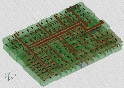
Factory layout planning in a team
The advantage of planning on paper is the simple possibility to plan as a group around the table and exchange ideas. This provides for a creative solution-finding process. Furthermore, simple paper templates can be created relatively quickly and at reasonable cost. The disadvantage of analog planning is, however, that no computers are used to solve complex tasks, such as material flow planning and effective saving and reuse of different variants and stages of work. Locally distributed working is significantly aggravated or even impossible.
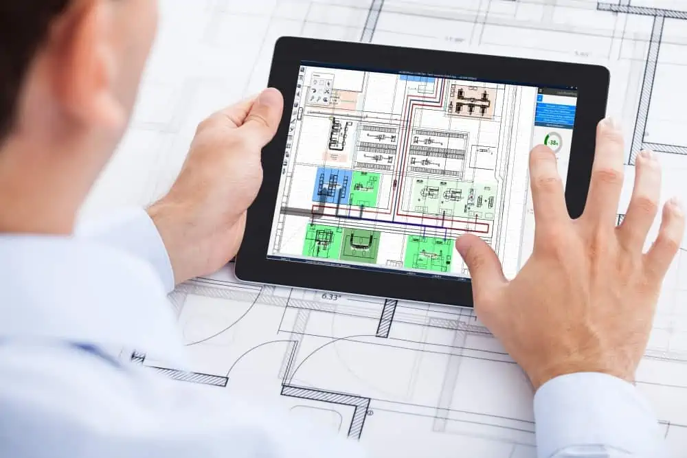
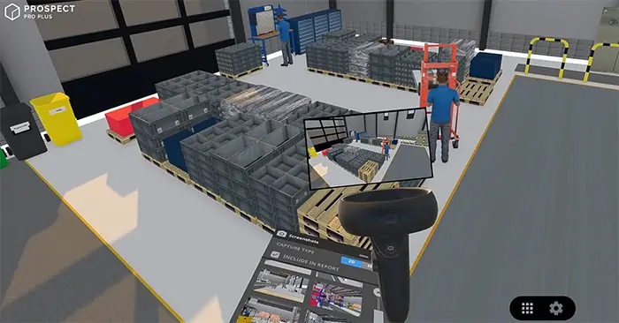
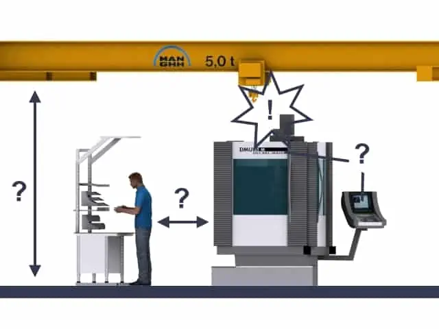
At this point, digital planning comes into play and overcomes the disadvantages of planning on paper and at the same time allows teamwork and exchange of ideas. Digital planning also expands the possibilities with reference to realistic 3D planning that can also avoid errors in the form of inadequate height clearances (gate too low, for example) and allows ADOC calculations and visualization of hundreds of transport relationships and other key parameters in planning once a person involved in the planning moves an equipment item in the layout. This significantly increases the quality and acceptance of solutions.
To be able to make the teamwork in paper planning digital, the software must be easy to operate, comprise an appropriate model library and also allow manual input on appropriate touch devices where necessary. It is thus possible to include significantly more people in the planning process which is important for the exchange of ideas and process of problem solving.
The benefits of a digital layout
Locally distributed working upon the layout
Simplified layout management by way of files
Quick comparison of layout variants
Adhoc calculation and visualization of planning parameters
Extended 3D and VR planning
Enhanced possibilities of presentation
Which layout types exist?
The ideal layout
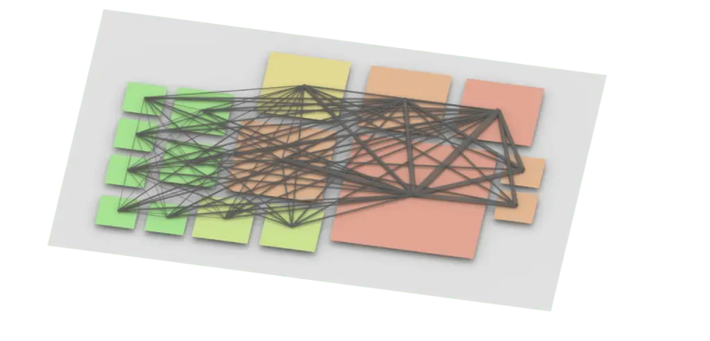
The ideal layout serves an initial rough structuring of the factory. It consciously ignores local framework conditions, such as an existing building structure or network of transport routes, and depicts a highly simplified solution as the ideal outcome. In the ideal layout, a design geared to the demands of production is given special emphasis by prioritizing areas and above all the shortest transport routes.
Required floor space or area
Material flow relationships
Organizational aspects
The block layout
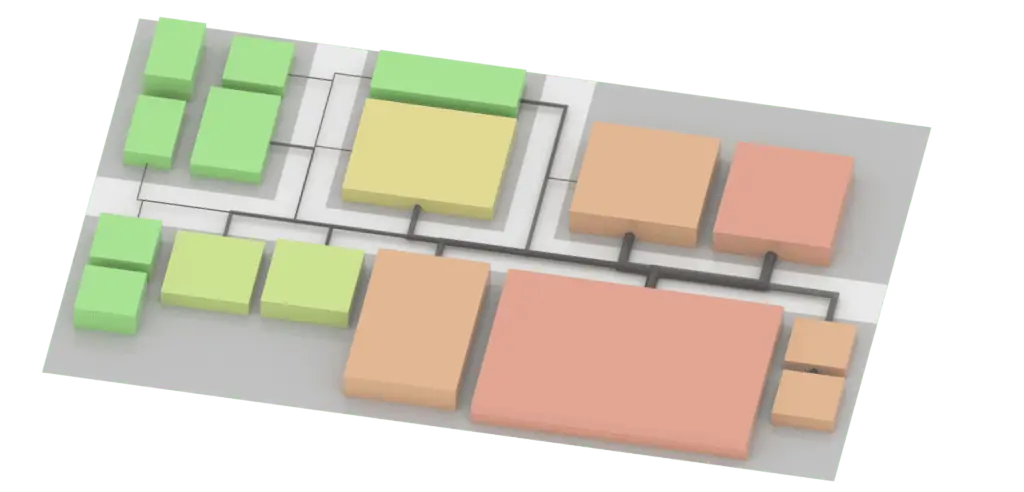
The block layout visualizes the real layout objects by way of simple geometric shapes. The block layout roughly visualizes a general concept for arrangement of the equipment in a building. It visualizes the local conditions of the individual manufacturing areas and their involvement in processes and the material flow. The block layout is ideally also used to specify the building design, including its form, floors, column spacing, sanitary and social areas, etc.
Required space or area
Material flow relationships
Local conditions and limitations
The fine layout
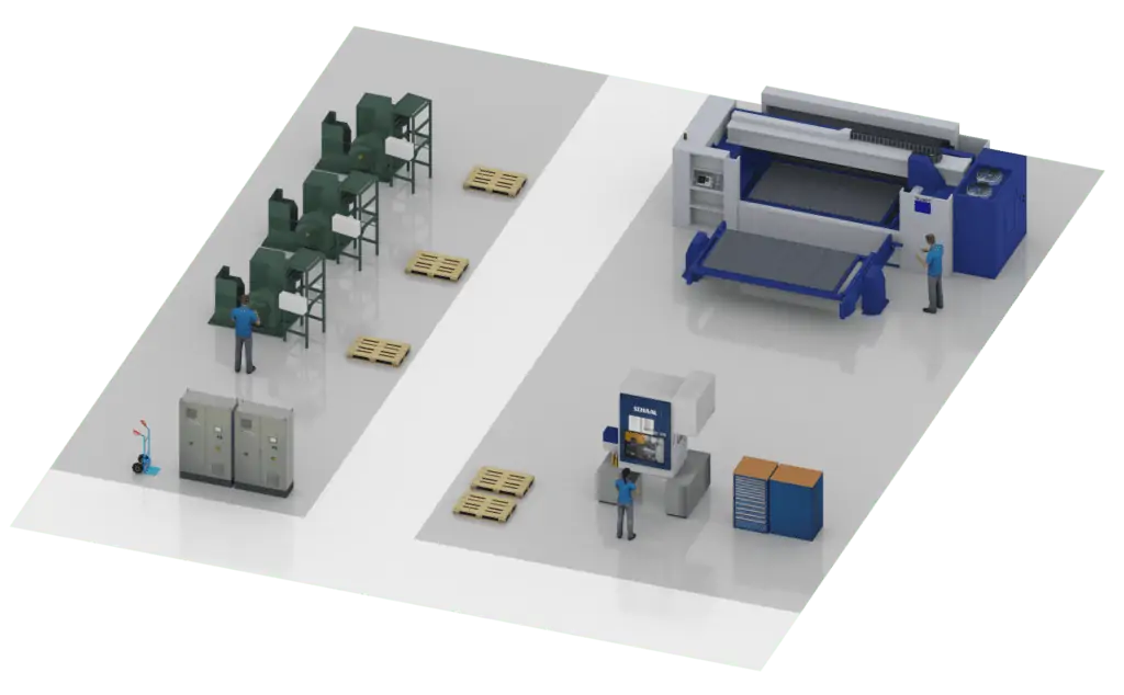
The fine layout is deemed to be a further development of the block layout and can already be part of detailed planning. Areas previously represented roughly are planned with details. Block diagrams are replaced by detailed equipment objects. It is the objective to create a realistic layout plan that can be implemented in a real factory. The fine layout is the basis for detailed planning as used as the basis by the media, escape route or building service planning.
The right basis is especially important for the fine layout. The coarse structuring should already be validated in advance to be able to avoid time- and cost-intensive changes.
The basic principle “top-down” is therefore very important in layout planning to be able to avoid fatal planning errors and reach an early start of production (SOP).
Top-Down Principle
“Start out roughly correct, rather than exactly wrong.”
Many major modifications are usually made in early planning phases.
Inexpensive concepts can be elaborated quickly with few layout objects.
Provides an initial material flow analysis and area balancing to validate solutions.
How do I determine the optimum layout for my factory?
How can I compare layout variants?
No matter whether ideal, block or fine layout — there are always different variants to compare. Transport efforts and area requirements are the two most important parameters, but transport crossing points, transport-system costs and special functional areas (e.g. cleanrooms) can also play a part.
To let the planner also weigh softer factors, software supports the calculation of key parameters and complex interrelations on the basis of a digital layout. Variants can be compared and selected very quickly on the basis of KPIs, and the remaining few discussed in detail by the team.
Two parameters lead the decision
Transport effort
distance × intensity across all relations
Area requirement
footprint and its influence on premises cost
How to obtain a digital factory model?
The objective of digitization is to create a consistent, readily scalable factory model, no matter whether two- or three-dimensional. Basis is a model library that ideally contains all factory equipment required for layout planning. The planning models must be properly dimensioned, easy to localize and identify and should be available in sufficient detail for factory layout planning.
Generally speaking, a distinction is made between building data and equipment data. Existing buildings usually only change to a very minor extent; newly planned buildings, however, can change significantly over the course of the planning process. For planning, it must be possible to disassemble a digital building model into its floors.
Equipment is used in layout planning in the form of movable layout objects and will usually remain unchanged. It is imported into the model library once as a planning object. More complex systems are disassembled into individual models such that the arrangement can be performed as desired.
What are possible data sources for planning models?
- Library of current inventory
- Documents and images
- Photos shot by digital cameras
- CAD data from architects & equipment suppliers
- Point cloud from laser scanning
The greatest challenge, in addition to the determination of the current inventory, is to enable the planner to utilize these digital data effectively. It is his task to identify the optimum arrangement in the factory. Creation of the required geometries and finally of the planning objects is a preparatory measure.
Why is the model library such an important preparatory measure?
Why the model library matters
Lets the planner concentrate on the planning task itself
Is the basis for an exact, easy-to-understand factory model
Captures expert knowledge (and is time-consuming to build)
Provides higher acceptance & safety for team solutions
The main principle of factory planning is “as detailed as necessary”. Appropriate models should be available in accordance with the planning phase. This can be simple arrangements of blocks (roughly visualized machining group in the block layout) or a detailed machine model from the equipment supplier (incl. control panel, doors, and signal lamp in the fine layout). Digital model libraries can be used and managed in a decentralized manner.
How detailed must a planning model be?
The decision depends on the planning goal. The following questions help to bring clarity:
Do I only plan in a single plane, where height is irrelevant?
Is the factory model the most important means of communication?
Do I need 2D or 3D models?
Which level of detail (LoD) fits my application case?
Equipment
The diagram below shows different levels of detail of a planning model for an injection molding machine in 2D and 3D as an example. The level of detail increases from the left to the right. The workload for creation and the quality of the planning model must be weighed up. The decision for a certain level of detail should primarily dependent on the attainability of the planning goal.
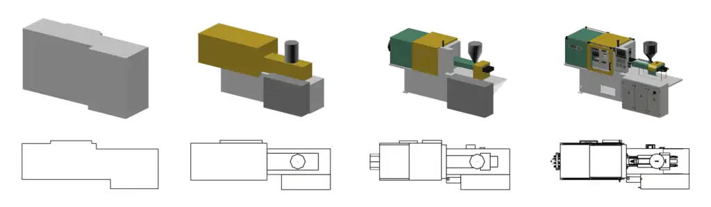
For example, a relatively exact arrangement of the equipment blocks, with consideration of the overall heights, can be realized with the 3D model at the first level of detail (left). A pure 2D representation would also be sufficient if heights are not important. It is not possible, however, to identify the individual components such as the material supply, the operator’s side or part heights. If such elements are important for the planning, the third level of detail (second from the right) would be better suited. In the 2D presentation, the operator’s side should be indicated by way of appropriate symbols. If the model must be identified very precisely and is intended for use in presentations, including virtual reality, the fourth level of detail (on the right), exclusively in 3D, is the ideal choice because details as in the real product can still be identified and properly support visualization at a scale of 1:1.
A high level of detail does not automatically mean a very large amount of data. Well optimized planning models possess only 1/100 to 1/1,000 of the initial data amount of the original product or CAD data to render possible the arrangement of thousands of objects in the digital factory model.
Buildings
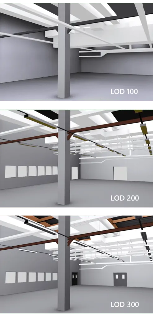
This similarly pertains to the data of buildings. The diagram below shows a possible level of detail in accordance with the corresponding case of application. The level of detail increases from the left to the right.
The first level of detail (left) roughly takes into account the limitations in the space both with reference to the area and to the height of the building service installations. If door and window openings are also to be taken into account in the planning, however, at least the second level of detail (center) is necessary, while a realistic visualization requires the third level (right).
Layout planning as part of quality management
The layout is also a digital document. It maps the factory, ideally in its current state or as planned in the future. Such a factory model can also be used to document the complete equipment, including its properties (designations, functions, investment, etc.). An up-to-date layout is thus an important element in the quality management of a factory and can serve as a platform for communication for all persons involved in the organization – both horizontally and vertically.
In many cases, the 3D view of a planning software helps to avoid errors in the planning and to support the factory operation. The following aspects are relevant:
Layout planning helps to support your work with:
- No collision hazard at heights
- Extraction units above workplaces
- Ergonomic workplace design
- Marking of storage areas
- Free transport routes
- Sufficient passage widths
- Lines of sight for warning labels
- Correct alignment of equipment
- Guaranteed escape routes
- Tidiness at the workplace
One Tool. Better Factories.
Plan your factory the easy way — from idea to 3D layout in minutes.
Drag & drop, intuitive navigation, no CAD knowledge required.