In philosophy and technology, ideal stands for a model of perfection. The eponym is the idea (lat. idea), the thought of the perfect. At the same time, the ideal hoovers in the space of the unattainable, and it is therefore often classified by pragmatists as an ambitious goal, which gradually erodes in practice. The theory of layout planning roughly follows this picture. It gives an idea of what the optimal factory layout should look like. The ideal layout can be calculated. It describes an arrangement of layout objects (e. g. machines, plants, production areas), where all the key figures of layout planning have reached their best value.
Here is where the pragmatism of the ideal layout begins:
- What are the key figures?
- Which degrees of freedom do we have by layout planning at all?
- What is the measurement variable to distinguish the ideal layout from other layout variants and thus make it stand out as the best solution?
And it goes on pragmatically: The ideal is confronted with reality. Reality creates restrictions that block the ideal in its practical implementation. What are these restrictions? Does it even make sense to design a factory layout without restrictions?
We want to briefly highlight this here in this blog, focusing on the practical importance of the ideal layout in factory planning.
What makes the ideal plant layout ideal?
Having a look at the degrees of freedom in layout planning, we see they are quite manageable. A set of dimensioned arrangement objects is given, which are to be positioned optimally to each other. The area of the objects is already determined by the dimensioning. The only size to design is the distance between the objects. Here we see that the shape of the objects has a significant influence on their distance from each other.
The space requirement as a cost driver
So is an arrangement ideal in which the distance between all objects is zero? Because in that case, the total area required for all objects reaches a minimum. It is like a puzzle, for example. Here, however, due to the shape and image of the arrangement objects, only exactly one position is ideal for each puzzle piece. If, on the other hand, shapes are variable, we will find different arrangements for the same set of arrangement objects, where the object distances are equal to zero. Consequently, a geometrically dense arrangement of all objects is only a necessary boundary condition of an ideal plant layout, not a sufficient one.
The influence of logistics
In this respect, it is necessary to use another measure to assess the perfection of a layout design. The consideration of cost drivers in the production process regarding the object distance guides very quickly to material flow and logistics. When there is a high transport volume between individual machines, their distance from each other is more important than the distance between objects with a low transport volume. Therefore, the transport volume we should use as a weighting for the object distance. All arrangement object pairs thus receive a priority derived from the material flow.
However, if the transport volumes are nearly the same, this prioritization will give equal preference. Then we need a further measured variable to determine the ideal plant layout. It is the number of material flow relationships of the arrangement objects to each other. The technical term for this is the degree of cooperation. It describes the extent to which a material flow system is linear in the form of a chain or more in the form of a network.
The transport effort as a yardstick for the ideal plant layout
Putting all this together, a priority for the arrangement of objects emerges, which is fed by transport volumes and logistical networking. This we use in layout design by applying so-called build-up or swap procedures. These are heuristics that guide the layout planner through the design process.
The result is a densely packed “patchwork”, a block layout. We evaluate its quality with the so-called transport effort. It is calculated from the product of all transport volumes with the respective distances to be bridged between the objects. The simple distance between the centers of gravity is used to determine these distances. This results in a simply measured quantity. Varying the arrangement of the objects, the transport effort changes. The smaller it is, the closer the arrangement is to the ideal layout.
How to create an ideal plant layout?
As simple as the concept of the ideal layout is, its development requires a certain data framework and some methods. In this respect, the question naturally arises as to the cost-effectiveness of ideal plant layout planning. To begin with, it is worthwhile. That’s why the data and methods required for the ideal plant layout planning we can use throughout the factory planning process. It also includes the optimization of existing factory layouts. Let’s take a look at the procedure.
Step 1: The functional diagram of the factory
The principle of the ideal layout planning is design follows function. The starting point is the so-called functional diagram of the factory. It describes the process-related interrelationship of the objects in the factory layout. For this purpose, we analyze the technologically necessary processes for all outputs of the factory, which are associated with relevant logistical effort.
Suitable data sources for the functional diagram are the target value streams for the whole factory. That means, as input we need the optimally designed production processes of all product families. The technologies used in the value stream create the resources to be arranged in the layout, e. g. as production areas (machine groups, assembly lines, etc.).
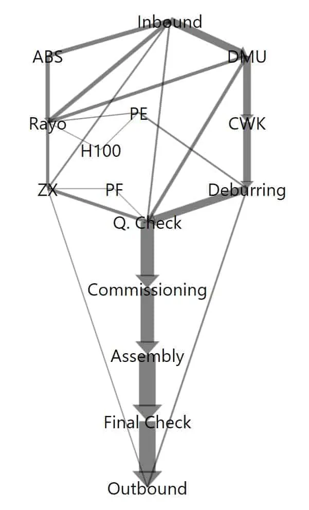
Step 2: The Sankey diagram
To determine the transport volumes, conceptual assumptions regarding logistics are helpful. Of course, we can also start from the pure mass or volume flow between the resources. However, since the value stream design already defines target transport lot sizes, at least the calculation of transport intensities between the objects of the ideal plant layout can be derived. This quantity illustrates the logistical effort between the objects in the functional diagram.
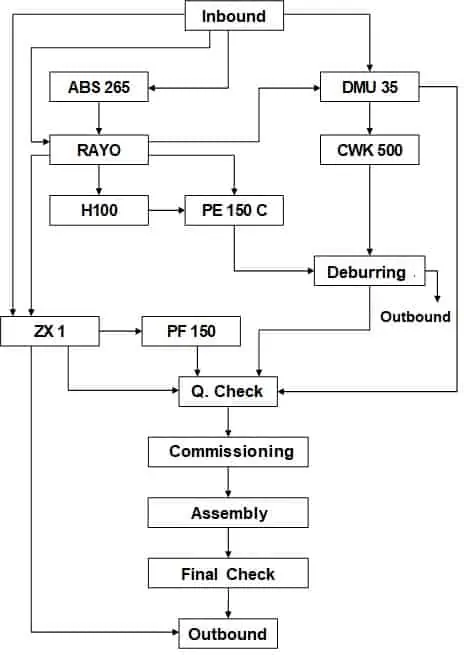
The result is the so-called Sankey diagram. In this diagram, the transport intensities between the arrangement objects resulting from all product families are summarized and illustrated in directional, intensity-proportionally thick arrows.
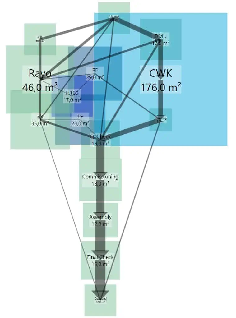
Step 3: The block layout
The considerations about the capacity of resources in the value stream design yield the space requirements of the resources (cf. line-back principle). So we have got the dimensions of all the arrangement objects required for the ideal plant layout. Now we transfer these dimensions to a block layout. Probably the block layout objects will overlap while using the functional diagram as a pattern.
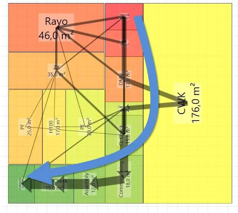
Step 4: The arrangement optimization
Finally, we have to find the ideal arrangement. Due to the basic structure of this optimization problem, this can not be solved fully automatically in a reasonable amount of time, even for layouts with only 20 arrangement objects. Therefore we use – as mentioned above – heuristics and determine first of all
- the arrangement priority of the block layout objects and
- the structure type of the flow system (network or line).
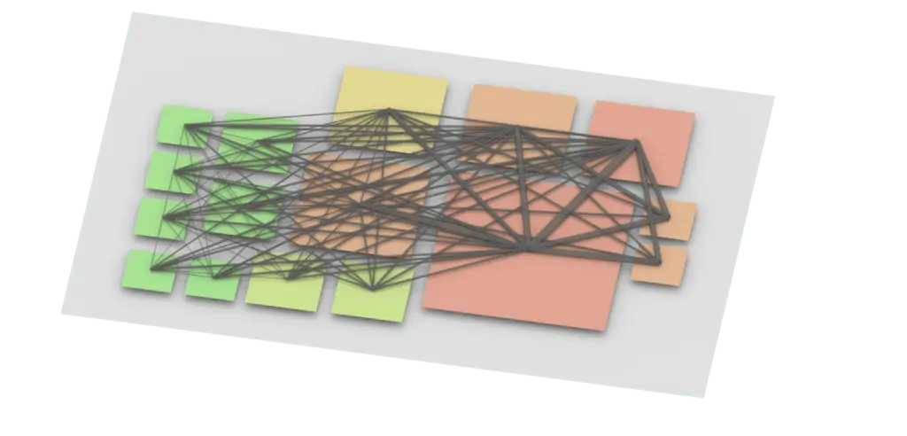
The following figure shows a visualization of the arrangement priority for the block layout we have seen above. The structure type is quite linear in this example. To visualize the structure, the layout objects are colored by the heuristic. In that way, the ideal line arrangement is given by lining up the blocks from red to green. Now we just need to position the block layout objects along this imaginary line in a minimal arrangement space.
All of this is usefully computer-aided using software that enables visualization of the arrangement priority and the layout to be changed while determining the transport effort in real-time. Only in this way we might create and evaluate different variants effectively. The ideal plant layout is the result.
The practical significance of the ideal plant layout
It becomes clear that the steps shown do not only produce ideal plant layouts. However, the procedure can also be used in the brownfield. For that, we reduce the degrees of freedom of the ideal layout planning by adding restrictions, e. g.
- building structure,
- given main transport routes,
- existing locations of heavy plant technology,
- given technical building equipment,
- unresolvable organizational constraints.
Many of these restrictions are only transparent to experts in the respective field. Moreover, they often cannot be easily described formally. So they can not be taken into account algorithmically by software. In this respect, knowledge input directly into the layout planning process is necessary.
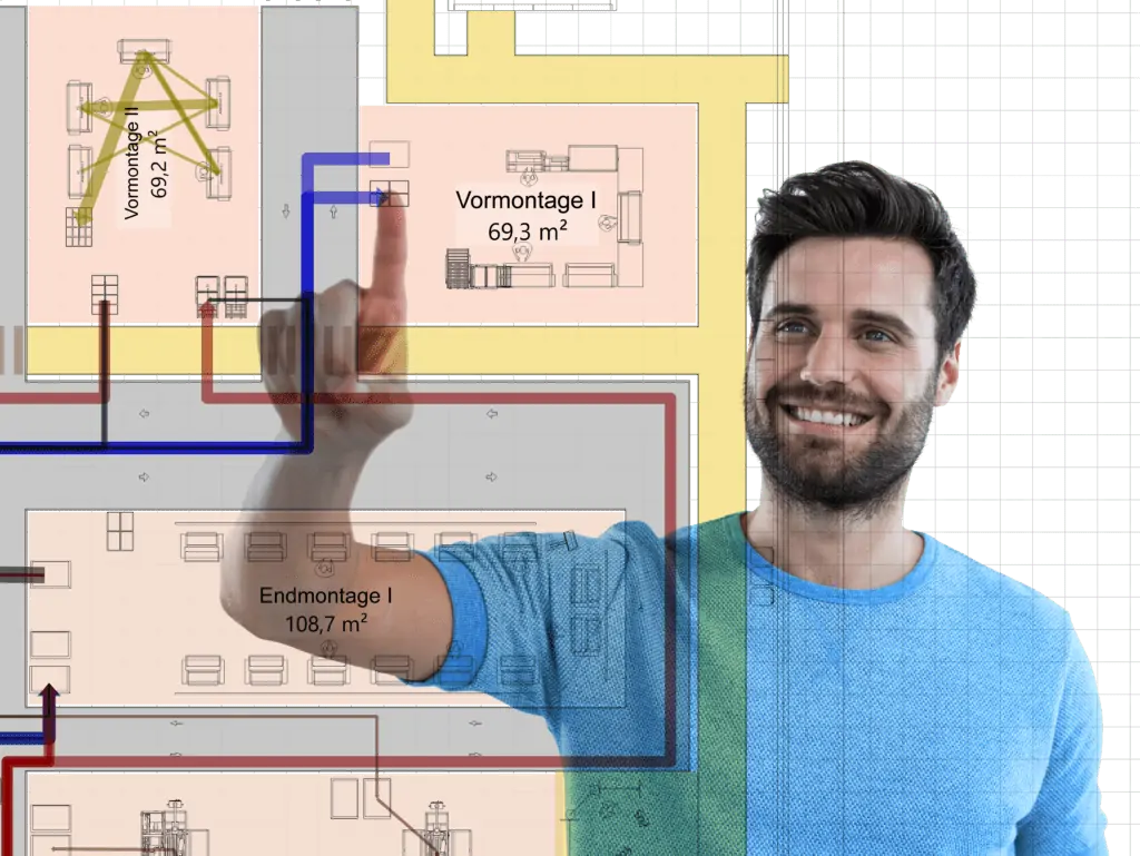
Teamwork is the method of choice. Modern digitization solutions for layout planning support the joint development and optimization of layout ideas. It doesn’t always have to be virtual reality (VR) or AR. After all, a workshop with block layouts to optimize larger factory structures is most likely to achieve its goals in 2D. Especially since the measurand transport effort and its data basis are relatively coarse and do not require any immersive modeling in the detail of virtual reality.
An easy-to-use digital solution with a large-format touch screen was already identified in research at the beginning of this millennium as a target system for workshops on a factory layout. With today’s hardware, it is not even something technically out of the ordinary. You can just do it!
Related topics: