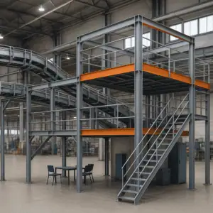
There it is again in the download folder, a 500MB zipped archive of a 3D CAD model. CAD stands for Computer-Aided Design. The supplier was kind enough to send me the CAD data of our newly purchased machine with all the assemblies and components in it. Not by email, of course, but via a download portal, because the file is simply too big. Unpacked, the machine model is 20% bigger and now this half gigabyte of data has to be included in my factory layout. 10 million command lines for just 6m² of floor space in my 12,000 m² factory production. What would happen if I filled only half of my floor space with such CAD models? 600 GBytes of data in a layout… well, even very well-equipped workstations in research would go to pieces to display that in 2D or 3D. Even the promised RTX graphics card from my administrator won’t help much. Do you know this problem?
CAD product data is not created for factory layout planning!
This article will therefore take a closer look at the practical handling of complex CAD product data in the factory planning environment. It is to be understood as a guide for production planners and suppliers. Today, efforts such as the digital twin often fail due to the sheer volume of product data provided by suppliers to the factory operator respectively a manufacturing company. The fact is that these models were never designed for the application of factory layout planning and have to be optimized. They were created solely for the production, assembly, and management of the respective product, such as a machine tool or a configured assembly table. Mechanical engineering is primarily about product design, including all mechanical components and electronics. The requirements could not be more different compared to factory design. However, the manufacturing companies, i.e. the factory equipment suppliers themselves, must be able to serve both domains in order to remain competitive. So how can this CAD data then be used meaningfully for factory planning?
When are CAD product data needed at all in factory design?
In early planning phases of factory design, a planner often relies on planning with abstract blocks. These simple models are provided by planning systems as a standard function. This is often completely sufficient for an initial structuring of the factory. CAD data are therefore not yet needed. However, as soon as the common understanding in the team becomes more important, detailed models for detailed planning are needed. For example, the concrete arrangement of production areas only becomes transparent if the factory equipment is also recognized as such. The following video shows why 3D data has a decisive influence on the success of factory planning:
CAD data from factory equipment suppliers is then a frequently used data source. These can be available as a 2D drawing (usually a building floor plan) or as a complete 3D model (equipment, building). Accordingly, manufacturing companies have to deal with product design data on a daily basis.
Reasons for optimizing CAD data
But can I also use this data directly? Unfortunately, in many cases this cannot be recommended for the following reasons:
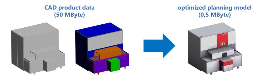
- technical reasons: the amount of data is simply too large. A typical example is a 3D CAD model of an assembly table in STEP format with a file size of 100 MByte. At this size, long loading times and delay in the 3D view are to be expected. A fully optimized model for layout planning would have a size of about 1 MByte, still acceptable is about 10 MByte depending on the overall scenario. Likewise, 2D drawings can contain overly complex derivations of 3D models and unnecessary drawing elements, which can have the same negative effect in the 2D view.
- planning reasons: the model does not correspond to the real object in terms of appearance, is different in color (e.g. monochrome grey) and thus difficult to identify. It may contain geometric elements (auxiliary geometry or variants, for example) that are not needed or even distort the footprint. Crucial planning information is again missing and makes communication difficult (see picture below).
If it doesn’t fit as an attachment in the email (max. 10 MByte), it is often too large.
Measures to improve the data quality of CAD models
For effective data exchange of 2D floor plans and 3D design data from third-party CAD systems for a planning system, the following two main points must therefore be considered:
- Targeted simplification of 2D floor plans and 3D design data
- Not available data formats and export settings
Practical hints in the following sections are not related to a specific CAD software or only where it makes sense to a specific 2D/3D format in order to be able to give generally valid recommendations to manufacturing companies and suppliers. The aim is to enable the direct use of third-party design data through these recommendations. Third-party design data is also generally understood to mean CAD data, because these usually originate from so-called CAD systems.
Product development CAD vs. layout planning of the factory
From a CAD software or product design to factory design, one changes to a completely different field of application, from product development to factory layout planning. The goals and tasks are different and so are the demands on the design data, illustrated in the picture below.
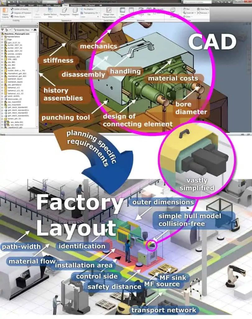
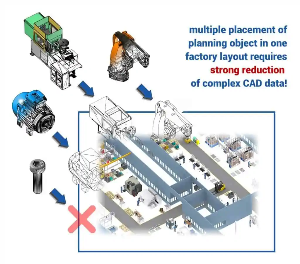
Whereas in product development often only individual models are considered, in factory planning several hundred or thousands of these products are considered simultaneously (see picture below)!
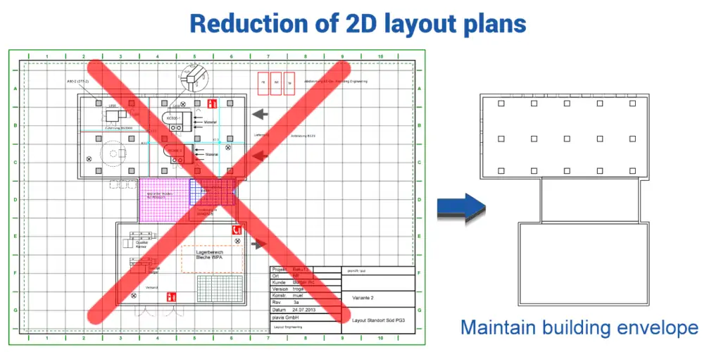
How does the simplification of CAD models work?
The complexity thus increases significantly in a factory layout. The product design data are only considered as equipment objects. Only the outer shell of the object is relevant. The simplification of this data can be done as follows, illustrated in some pictures.
Lean planning models facilitate the work enormously and ensure the expandability of your layout.
If, for example, design models contain different variant constructions, then only ONE variant may be exported in order not to create an overlay of several identical objects. Auxiliary geometry and other construction elements that do not belong to the factory equipment or the building must be removed.
Procedures for simplifying 3D CAD models
Below are illustrated some possible processes for simplification, followed by an explanation of the effect.
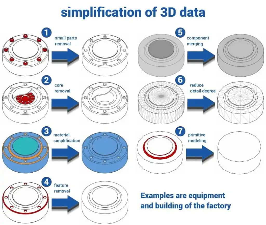
The aim of this simplification is to preserve the outer shell for identification of factory equipment (size, type of machine, operating side, manufacturer, for example) or a structure (walls, doors, light openings, columns, roof).
- 1 and 2 are very effective in enabling lag-free rendering and significantly reducing loading time.
- 4, 6 and 7 are very effective in significantly reducing loading time.
- 3 is a detail optimization that can support lag-free rendering.
- 5 should only be used after applying 1, 2, 4, as merging leads to very complex objects.
CAD software sometimes also offers the generation of a so-called “shrink wrap”. This attempts to generate an envelope model from a complex design data set. In many cases, the amount of data can be significantly reduced. However, success here also depends on the performance of the software and the respective data set. Open structures with many details are always more difficult to simplify compared to a completely enclosed machine. Often, the CAD software delivers monochrome envelope models whose information content may not be sufficient. In any case, it is worth exploring the possibility, even if it is not a miracle cure.
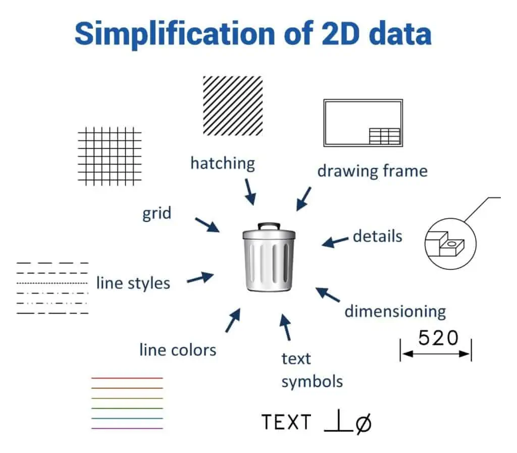
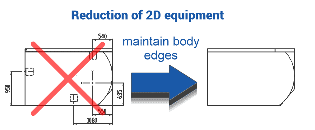
Procedures for simplifying 2D CAD drawings
The following picture shows typical drawing elements that often do not add any planning value and can significantly slow down the interaction with the factory layout or, ideally, can be taken from a standard library in the planning system through movable planning objects. A planning software offers, among other things, its own configurable grid, dimensioning function, text objects that can be used flexibly by the factory planner. Here it is important to weigh up which static information should really be included by asking the following questions:
- Does the information serve the purpose or goal of my factory planning project?
- Does the information support the ease of understanding of my layout?
- Is the information subject to frequent changes in the factory planning process?
By greatly simplifying the 2D floor plans and 3D product design data with a focus on the essentials, the planner gains the following advantages:
- Delay-free representation with potential for expansion
- Only information relevant for planning
and thus a significantly higher planning quality overall, which leads to better solutions.
Guide values for simplified CAD models
Guide values for polygon and object numbers of 3D models for equipment based on the standard size of 2x2x2m or approx. 10m³ volume.
The following graphic shows the influence of the level of detail (polygons) above all on the amount of data and thus the loading time and the number of objects of a model, which above all has a great influence on the delay-free display. If exported models are in the green range, even larger layouts with several halls can generally be built. In the yellow range, smaller scenarios such as a production island or a hall can still be represented well. In the red range, the models should definitely be simplified before use in the planning system if larger scenarios are to be represented. A factory planning system should support the planner with comprehensible instructions when importing CAD data.
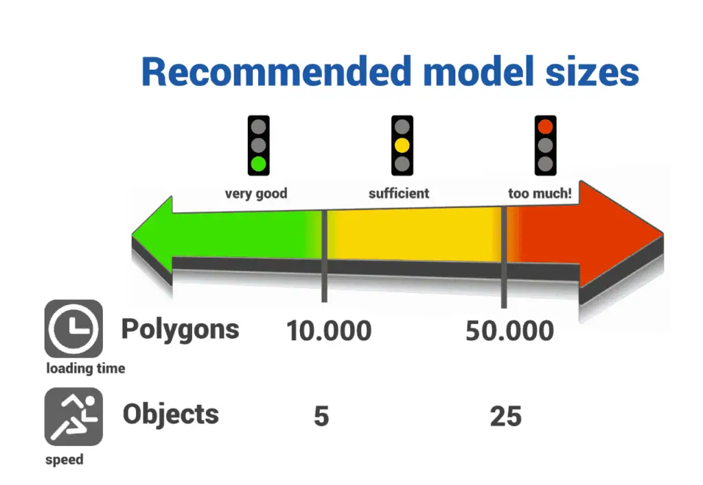
Please note that a building envelope or very large systems are special cases that can also be in the red range due to their size, as they cover a much larger area in the layout and are usually only used once in the layout. The limit values given are to be understood as guide values, always also depending on the performance of the respective system.
CAD data formats and export settings
When models have been sufficiently simplified, they can be imported into the factory planning system and made available as planning objects. The success of an import also depends significantly on the complexity of the imported CAD data. As a rule, a 2D derivative or 2D view is automatically generated from 3D CAD data. The delay-free representation is largely dependent on the complexity of the 3D design data.
If possible, try out different export formats from the respective CAD software.
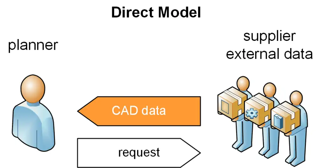
The following is an example of the available import formats in the visTABLE®touch software. Based on these formats, I can approach my supplier and coordinate and test a suitable data format.
2D drawing formats
| description | file extension |
| AutoCAD DWG | *.dwg |
| Drawing Interchange | *.dxf |
3D model formats
| description | file extension |
| VRML 1.0/2.0 | *.wrl |
| AutoCAD DWG | *.dwg |
| AutoCAD DXF | *.dxf |
| Wavefront OBJ | *.obj |
| 3D Studio Scene (3DS) | *.3ds |
| Stereolithographie | *.stl |
| Collada | *.dae |
| STEP | *.stp *.step |
| IGES | *.igs |
| Industry Foundation Class (IFC) | *.ifc *.ifczip |
| Jupiter Tesselation | *.jt |
Recommendation for CAD formats
Not all STEP is the same. Data quantity, colours, assembly structure, each software writes or exports data differently, even if it uses the same container format. Therefore, try different export formats in the respective CAD software if possible to achieve the best data quality. Commonly used formats for buildings and equipment are:
- STEP
- DXF/DWG
- IFC
If the CAD software also uses textures (image files), the following formats can save or supply them:
- VRML1.0/2.0
- Wavefront OBJ
- Collada
When exporting to STEP or IGES, please note that these are always exported as BREP Manifold Solids and under STEP in profile AP214 or if supported also the newer standard AP242. If possible, please avoid the export of shell objects or NURBS surfaces or also the export of auxiliary geometries that do not belong to the equipment or the building.
Furthermore, in CAD systems, if available, the level of detail should be set to the lowest level (e.g. Creo Elements VRML Export Detail Level Low). This allows you to significantly reduce the amount of data or polygon count. This is especially important if the model contains a lot of curved surfaces (see also “Methods for simplifying 3D CAD models” above).
Engage service provider to simplify CAD data
The reduction of CAD data requires engineering knowledge or a lot of experience and appropriate software and hardware to process the complex data sets. Original CAD product data (no shrink-wrap or welded models), which can quickly be several hundred MBytes in size, must often be reduced to 1:100 or even a 1:1000 of the original amount of data, while at the same time preserving installation space, factory planning information including a high-quality representation for identifying the equipment.
Save your time for actual planning and creating solutions.
Then it is often advisable to call in professional service providers or, if possible, to appoint someone internally for this preparatory task. In practice, however, the latter is often not so easy to do because, for example, a design engineer is already well occupied with the actual product development in-house. However, it may then be possible to carry out at least smaller tasks in-house and to outsource the preparation of complex standard catalogues with a long service life. In this way, CAD data can ultimately serve as a valuable data basis for the planning of your factory, even if it was not actually intended for this purpose.

related topics:
Using online 3D CAD models for layout planning?
5 Methods for 3D modeling of equipment for layout planning
What you should definitely know about Factory Planning
What is the right app, CAD system or planning software and when?