
3D models in factory layouts often come from a wide variety of sources. These include CAD data from the supplier, such as 3D STEP or 2D DXF and DWG. But 3D models from the visTABLE® model library also supplement a layout. This heterogeneous mix is normal in practice and makes it possible to achieve the set planning goals.
However, there are also cases where the supplier does not deliver, the data supplied is too large and cannot be used. If nothing suitable can be found in model catalogs or the budget for a laser scanning survey is not sufficient, another option is needed. Creating 3D models for planning yourself is one such solution.
Modeling with standard models in the visTABLE® software
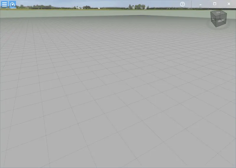
The visTABLE® software provides numerous catalogs with many “ready-to-use” 3D models for layout planning. But if I can’t find the 3D model I want here, there are also many basic elements for creating my own models or modules. Then visTABLE® can also be used like an app to create simple 3D models.
Tip: The last section of the article contains important information on handling modules, especially merging.
The following model catalogs are particularly interesting:
- 3D basic solids
- Block layout
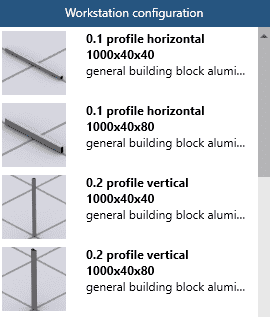
- Workstation configuration
- Annotation
- BITO
- Production accessories
- Pipes
- Pipe and joint system
- Steel structure
- Workbench configurator
Each of these catalogs offers basic modules for creating your own models for layout planning. These are specific to a particular purpose, but can also be used universally. This is comparable to a bag of Lego bricks. The only difference is that these can be scaled as required in the visTABLE® software and can therefore be optimally adapted to your own requirements.

These building blocks do not even have to fit together exactly as in reality, but can also be pushed into each other without breaking anything. This enables very flexible modeling of every conceivable shape as an outer shell. Ultimately, it’s all about the correct footprint and height information for equipment. If my 3D model meets these requirements, I already have a very good basis for layout planning.
A few pieces of data are needed as a starting point
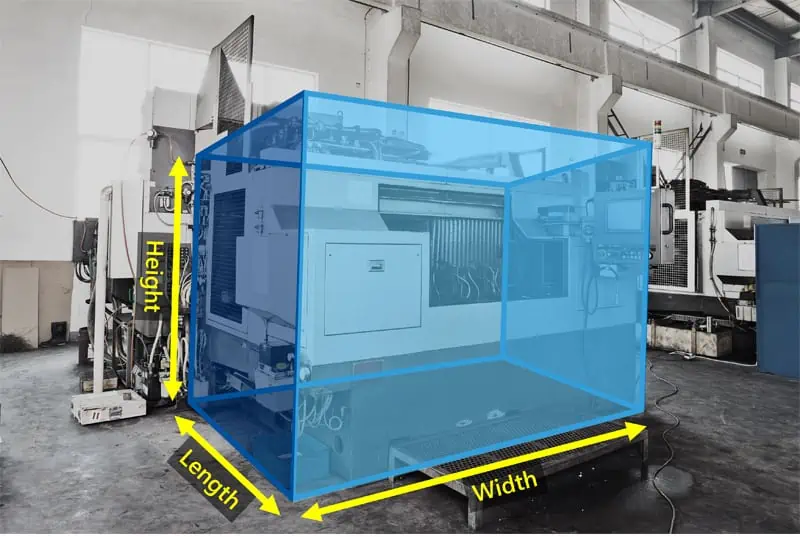
At least the geometric dimensions of the equipment should be known. Length, width and height are the minimum requirements for a 3D model.
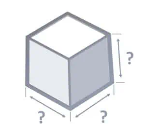
Secondary dimensions such as the height of a table top or the projection of an auxiliary unit can also be transferred to a 3D model. A few basic dimensions are often enough to create a sufficiently accurate model. Alternatively, you can also work with a mixture of technical drawings, photos and measured dimensions. Below I show 4 practical use cases:
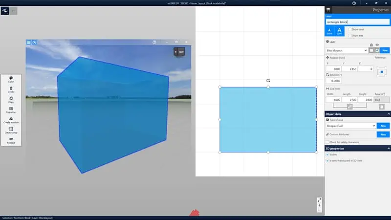
Example 1: Placeholder – the simple block model
The block model is the simplest way to create a 3D model. If I know the length, width and height, I can create a colorable 3D block within seconds. A “rectangular block” from the “Block layout” catalog is used below. These models have the advantage that they can also be displayed semi-transparently. However, they can also be set to opaque (“Is semi-translucent in 3D-view” off) via “Properties”.
Please note that these models are automatically assigned to the “Block layout” layer and the coloring is visible in 2D and 3D via the “Color” function as long as they are not merged. They are intended as placeholders for the installation space of new equipment and areas in visTABLE® in block layout planning. If only equipment is to be modeled, then these objects should ideally be assigned to another layer such as “Objects”. The last step is to merge the generated module. Alternatively, there is the 3D model “Cuboid” in the “3D basic solids” catalog, but this only allows an opaque representation.
Blocks generally have a very low information content in planning. More information can be added via other 3D blocks to subsequently form a so-called module in visTABLE®. The “Annotations” catalog with the “text field” and the “Main control panel” and “Secondary control panel” in the visTABLE® software is helpful here. The labeling and symbols in 3D add important planning information and allow me to better identify the real object.
Block models are particularly suitable in early planning phases in order to concentrate on the essentials. Or they can be used as placeholders in the event of poor data availability, which can be replaced by a detailed model at a later stage.
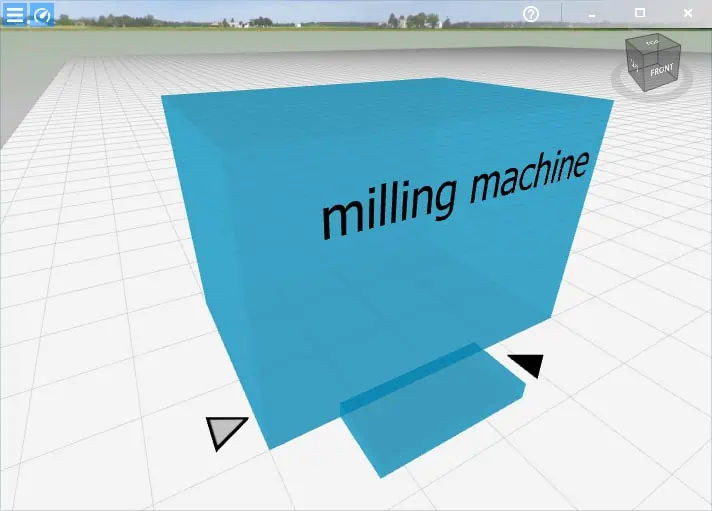
Example 2: Modeling equipment without digital data
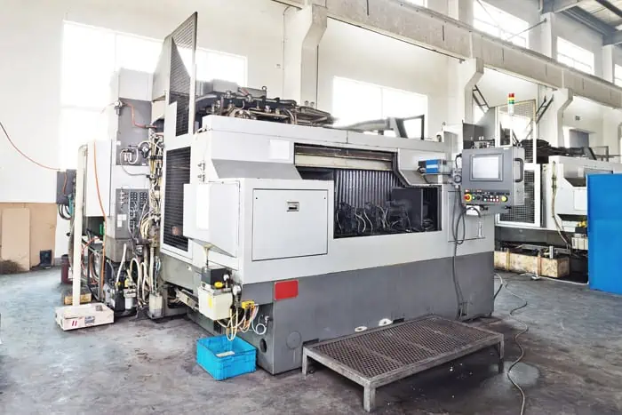
Do you have a machine in your factory and no digital data? Then in many cases the equipment can be measured directly. Let’s take the photo example from above.
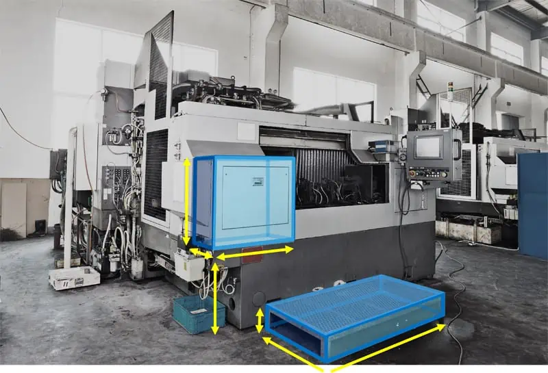
This does not even require expensive laser scanning. A tape measure or handheld laser measuring device and smartphone for photos are sufficient. Which and how the measurements are taken is less important. With the “3D basic solids” catalog available in visTABLE®, the machine can then be easily displayed in a simplified form.
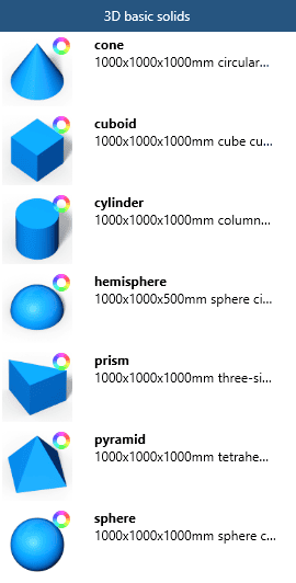
This extended block model is more complex to model, but provides a better visualization of the equipment in the layout planning. This is where I decide whether the effort is worthwhile in the current planning phase. The following is a possible result using only the 3D models “cuboid” and “prism”, and an auxiliary dimensioning.
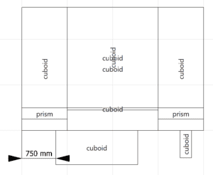
The actual modeling is carried out by modifying the 3D basic solids used and then positioning and rotating them. The following functions were mainly used in the example shown:
| Interactive moving | Placement of blocks in x and y with object snap |
| Interactive scaling | Fitting objects based on other geometry with object snapping |
| Lift/lower (3D view) | blocks that lie above the dark-colored base |
| Tilt (3D view) | Blocks that lie above the dark-colored base |
| Properties | Adjust length, width and height, color via 3D properties |
| Model search | Enter “basic solids” to find catalog 3D basic solids |
Example 3: Work table from illustrations and photos
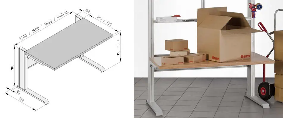
In this case, we have a technical illustration with dimensions of different variants and a photo where the colors and materials of the equipment are recognizable. Here too, a rough 3D model can be quickly created with the help of a few basic building blocks from the “Workstation Configurator” model catalog and the cuboid from “3D basic solids”.
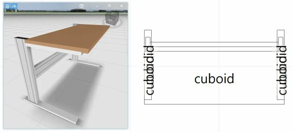
The CAD illustration provides secondary dimensions for the table, which may be important. However, it should be noted that the actual design may differ from the CAD data. Here too, the effort and benefit in the project must be in good proportion to the intended goal. In this case, the 3D model could be reconstructed with only 8 objects. Standard profiles for uprights and cross beams are clearly recognizable.
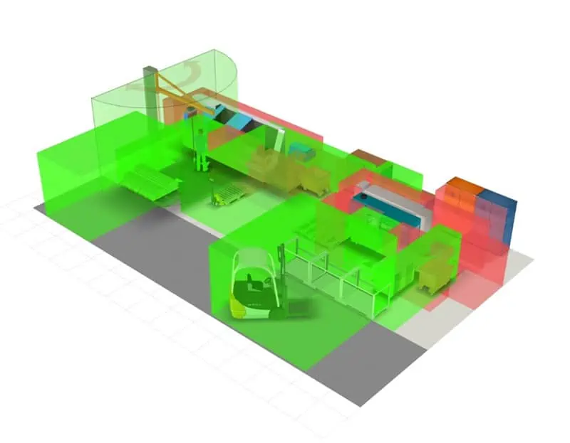
Example 4: Creating placeholders for CAD models that are too complex
It is quite common for factory planners to receive very precise 3D data from the machine supplier, but this data is far too complex to load directly into the factory layout.
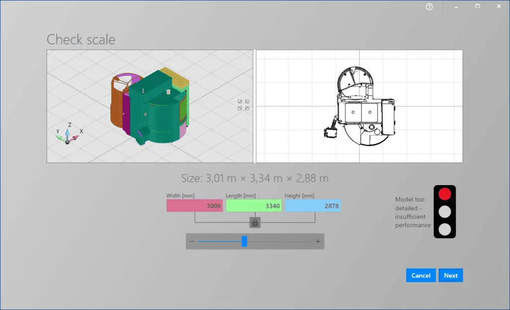
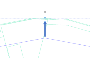
The advantage here, however, is the very precise reference that serves as the basis for a placeholder model. Based on the 2D CAD representation, I use the object snap to place and scale the basic bodies quickly and accurately.
Here, too, it is important to make a conscious decision about the level of detail with which the equipment is to be modeled. For example, rules such as
“Only build elements that are not smaller than 200mm, everything else is only modeled as a block or bounding box.”
This allows me to model an optimal 3D model with reasonable effort, as can be seen in the following result:
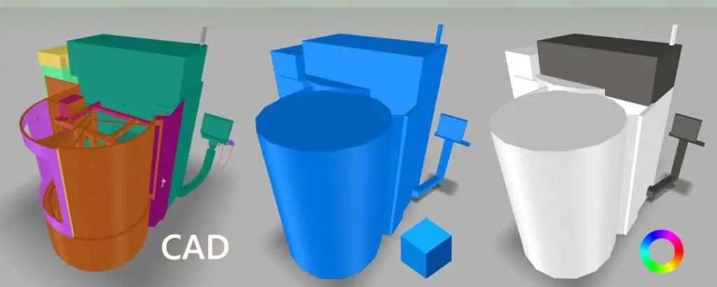
At the end, the 5000 times more complex CAD model is simply deleted from the layout and planned with the slim “low poly” placeholder. The installation dimensions are guaranteed and I don’t get a bottleneck due to overly complex data in the layout planning. In this specific example, the visTABLE® model library even contains a ready-to-use 3D model of the machine with a higher information content.
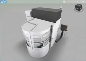
The simplified 3D model of basic bodies also contains the basic geometric structure and coloring of the equipment and can be used as a planning model right through to detailed planning.
Final module creation and storage in a separate model library
The result of all the methods described is always one or more individual objects. Geometric shapes and extended planning information can be combined. For example, additional surfaces or polygons can be used to create functional areas such as swivel areas, operating and maintenance areas during model creation. It should be noted that this planning information should be placed on separate layers. This makes it easier to isolate the information from the geometric model.
Finally, a module is created to make composite models available in the model library. Select all objects of the 3D model and create a module with the “Create module” function. After specifying a name, the module is automatically stored in the “Storage” catalog. The model can now be copied or moved to a suitable catalog using the ObjectManager. This can also be a shared library in the network, for example.
Merging the module
Merging ensures that the individual models of a module are inseparably combined into a single monolithic model. The software calculates a new 2D derivation (floor plan) for this purpose. Layers are also merged and 2D colors are removed from the floor plan.
TIP 1: Modules consisting of a large number of 3D components can significantly impair performance. Therefore, each generated module should be merged according to its real monolith structure. For example, the machine structures and associated functional spaces should each be transferred to individual merges. These can then be distributed to different layers when used in layouts.
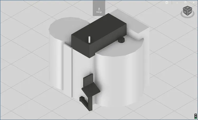
Open the module to be merged in the Object Manager by double-clicking on it and click on the “Merge” function. The ObjectManager now creates a merged copy. The original module is retained if changes are to be made to it later. This can significantly improve the display performance in visTABLE® in 2D and 3D.
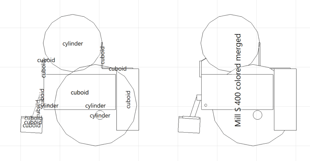
In the image above, the optimized 2D display can be clearly seen on the right. It is now easier to recognize hidden objects and there is only one object name. A single model is also much easier to handle in layout planning because it is no longer necessary to select several individual objects or form a group.
Conclusion on 3D modeling in visTABLE® for factory planning
In planning projects, it is always important for factory planners to remain capable of acting. Thanks to its extensive model library, visTABLE® can also be used for 3D modeling with standard elements to create your own 3D model libraries. The lean 3D models from the visTABLE® model library are also a great advantage. This allows me to avoid technical bottlenecks that can occur over time with a constantly growing layout using complex CAD data. In practice, this often results in a mixture of standard models, my own models and imported CAD data. With the right mix, I always remain capable of acting.
I hope this article helps you in one of your next planning projects. Because even if you don’t seem to have any 3D models to hand, this option is always available to you.
Further articles on the topic of 3D modeling:
- Visual 3D and 2D representation of factory layout information
- Planning and visualizing sanitary facilities in a factory
- Designing virtual factory halls in system construction
Related topics:
- The importance of space utilization in the factory
- Rough layout vs. fine layout
- What is a block layout useful for in factory planning?