Of course, the questioning title of this blog is rhetorical. Because in recent decades, both the way plant floor plans are created and their potential benefits have changed considerably. The reason for this – you guessed it – is the developments in IT and digitization.
The impact of digitization on plant floor plans
If we look back to the time of the turn of the millennium, the factory layout was just one of many documents describing the structure and function of the factory. At that time, it actually had the character of a drawing in the sense of documentation where something is arranged in the factory. It was an essentially geometric representation of the space condition. Often, for reasons of expense, this was also only executed as a two-dimensional floor plan of the machine arrangement. In addition, further documents were necessary, e.g. equipment or inventory lists, maintenance plans, room books, or CAM information on the plants.

Technically, digital floorplans of plants have often been realized in CAD systems. However, CAD applications were initially developed as digital drawing boards, i.e. they were intended to enable technical draftsmen to generate their documents computer-aided. Consequently, the data models and formats of CAD systems today are still oriented to the basic requirements of technical drawing. Line types and thicknesses, computer-aided dimensioning functions, implementation of technical drawing standards, and the like are the focus.
For a long time, CAD systems were perceived and used as universal tools for all digital modeling in architecture as well as in mechanical engineering. Especially since they could increasingly be used for three-dimensional drawing. In this respect, it is not surprising that many factory layouts are still available today in the AutoCAD format DWG or in DXF. Because with these formats, technical drawings from architects and factory planners could be merged.
Is there a universal tool for every planning task?
Please see the blog:
What is the right app, CAD system or planning software and when?

But in the course of digitization, new requirements developed. Information had to be integrated that went beyond the content of a classic technical drawing. The geometric image of a piece of equipment and the dimensioning of its dimension and position in the production hall thus evolved from the dominant informational core to one of several components of a more comprehensive digital model of production.
The consequence is that the plant floor plan loses the character of a technical drawing in the course of digitization. This, of course, has consequences. These are reflected both in
- information technology as well as in
- organizational
perspective in layout planning. We want to discuss this.
The IT aspect of the plant floor plan
If information is to be added to the drawing-based representation of production, the IT systems not only have to be more powerful, but it is also necessary to fundamentally question which information technology basis is the most suitable for which type of information. While the plant layout drawing requires a data model of technical drawing, this will no longer be sufficient for a more comprehensive digital modeling of a production site.
The construction industry as a pioneer
A pioneering role can be attributed to the construction industry. It was recognized early on that a paradigm shift in modeling is necessary for digital architectural models. As early as the 1970s, people began to break down buildings into their typical building elements and describe them digitally. We call this object-oriented modeling. The result was the object-oriented digital building information model, which is increasingly becoming the standard in construction planning and execution under the abbreviation BIM. This model is standardized internationally in the ISO format IFC (ISO 16739 – Industry Foundation Classes).
The core of IFC is that each component of a building is classified as a so-called BIM object in a defined structure. Similar objects are grouped into classes, whereby each individual object of a class can be distinguished from others by its properties. A GUID identifies each object in the data model. The geometry of each component is only one of many properties of the BIM object in this modeling approach. The overall geometry of the structure is therefore then obtained by assembling the individual BIM objects according to the structure standardized via IFC.
In contrast to technical drawings, where meaningless lines only produce a structure in their context, which is usually subsequently introduced into the digital drawing as information (e.g. as blocks), in object-oriented models such as BIM, each geometry is assigned to an object from the outset.
This approach has the unbeatable advantage that individual components can be developed in isolation during model creation. The building trades use so-called specialist models for this purpose, e.g. for the building envelope, the technical building equipment, or the supporting structure. These specialized models follow the IFC structure and can thus be compared with each other in a coordination model.
The success of this modeling strategy can be seen in a wide range of projects around the world. Without BIM, modern architectural icons would be unthinkable. This is also due to the fact that a large number of highly specialized experts have to work on such a building design, each using their own specialized software. Some of the resulting specialized models cannot be forced into the form of a technical drawing.
BIM for the digitization of factory layouts?
From an information technology perspective, plant floor plans are comparable to architectural models. Their structure also follows that of a system configured from elements. Nevertheless, there are differences in architecture. Objects of a factory layout have different and more diverse relationships with each other than the components of a building, which are strictly subordinated to a building structure.
Possibly this is also the reason why standardization in the modeling of factory structures has not yet progressed so far that one can already use an ISO standard for it. This makes it more difficult, especially for software manufacturers, to develop coordinated products. The software offering for factory planning is therefore relatively small compared to solutions for BIM.
Some companies are therefore using BIM tools to implement factory planning, especially for new manufacturing sites. However, from an information technology point of view, the same disadvantageous effect occurs when drawing plant floor plans with CAD systems: The digital model does not completely match the purpose and can therefore not be used to the necessary extent to answer relevant questions.
The information in the plant layout
Please see the blog:
Rough layout vs. fine layout

It will therefore be worthwhile in any case to analyze one’s own requirements precisely when selecting the software for planning plant floor plans. After all, the geometric mapping of the layout and perhaps some relevant machine data is in many cases only the proverbial tip of the iceberg for such a transformation-intensive system as the factory.
The organizational aspect of digitizing plant floor plans
Factories are alive and constantly changing. Knowledge about the factory is distributed in many minds. Floorplans create an orientation framework. They visualize what is where. With today’s technology, it can be used as a digital information and communication basis. If we compare the character of this model with a map in the change of the last decades, then perhaps it becomes clear which changed organizational requirements arise from it also to the production of plant layout.
Qualification of layout creators
In the past, a map was published by a publisher for the respective purpose, usually printed on paper. For example, there were hiking maps, bicycle maps, and car maps. Geo-information was collected for this purpose and presented enriched with corresponding expert knowledge. Organizationally, this process was functional: There were experts for both the design and the implementation of the map. While the editorial staff collected and prepared the information, the actual map was created by the specialized print shop staff, often in painstaking detail, using knowledge about the specifics of the print shop facilities.
It was similar to the plant floor plan: The information on the geometry and location of the equipment was provided by various experts and then converted into a technical drawing by specialists in CAD.

Today, many people no longer use printed maps; they rely on Google Maps, for example. Expert knowledge of map printing is thus required to a much lesser extent, as is the technology and organization for it.
In exactly the same way, the tasks of technical drawing have also changed over the years: A function-oriented qualification for drawing arbitrary CAD models has become an object-oriented one. Today, we usually find design and modeling of e.g. technical components combined in one and the same qualification, e.g. as a (partial) designer in product development or as plant designer or industrial engineer in production engineering. The qualifications differ according to the objects to be designed, they are object-oriented instead of functional now.
Division of labor in creating factory layouts
This has also changed the division of labor. Digital models are no longer created centrally by a handful of specialists; instead, almost everyone digitizes something: letters, tables, and, of course, parts of the plant floor plan. Thus, the division of labor in digitization is also becoming object-oriented.
This is accompanied by the loss of a relatively centralized set of rules for modeling itself. When everyone creates digital models, their structure is influenced only by the individual skills and abilities of the authors and the rule set of the software used. Digital compatibility consequently has to be secured by the organization as long as the software used cannot use modeling standards, as outlined with IFC for the construction industry above.
Now it would be fatal to judge this as a danger. After all, it is precisely in the factory layout design that the expertise of those involved is required. In addition, studies have shown that participation effects can be used excellently, especially in factory layout planning. It is much more important to intelligently link the resulting digital fragments to the factory layout.
The digital plant floor plan in practice
In practice, this means using a hierarchical model of the production site as a guide and creating responsibilities for individual levels or elements of this system within it. In this way, proven design principles for factory layouts can also be implemented in organizational terms.
- Top-down (from the rough to the fine);
- Bottom-up or line-back (from the core of value creation to the periphery).
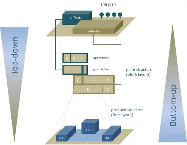
From an organizational perspective, the top level of the factory layout model should be the responsibility of just a few planning experts. In contrast, there are a large number of subject matter experts who model fine floor plans and details of individual departments or production cells. These fill the lower level of the model, working in a distributed manner.
Our video shows how this can be implemented with the help of object-oriented planning systems.
Conclusion
If one considers the information necessary for planning a factory layout and develops a digital model from it, the geometric representation of the plant floor plan represents only the tip of the iceberg. This is true even if the factory layout is digitized in a three-dimensional CAD model or in a BIM model. This is because layout planning processes rely heavily on the division of labor and expertise. With the given complexity, those involved can usually only capture and use parts of the overall information, and the same applies to the generation of information for a plant floor plan. Therefore, become aware of the importance of a digital model for your production site and consider not only the available tools but especially organizational development when thinking about digitization.
Related topics:
- Rough layout vs. fine layout
- Digitalization of production: How to
- BIM Software in Factory Planning
- How to organize factory layout planning?