In the industrial manufacturing engineering process we too often experience pigeonhole thinking. If a new component is to be manufactured, the following engineering procedure starts:
- First comes the hour of the product design engineer.
- If the part is perfect, the manufacturing and possibilities for automation are thought through, if necessary with the help of suppliers.
- Once the manufacturing facilities are available, space is found for it in the factory.
- If there is no space for it, it has to be rearranged or even reorganized.
Sounds normal to you? To me, it sounds like wasted potential in engineering. Because in step 3, there is a breaking point in the development process. For example, steps 1 and 2 are often well interlocked on the part of product engineering. This is because established engineering procedures for product development that is suitable for manufacturing and assembly provide orientation.
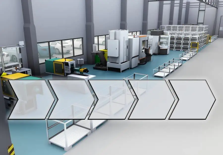
But when it comes to integrating the manufacturing and logistics system into existing factory structures in step 3, decisions are often made on the basis of gut instinct and the experience of the manufacturing engineers. However, these are sometimes complex arrangement problems that – like the actual product development – can be processed and solved just as methodically. The following three guidelines are intended to help production engineers with this.
1. Value stream from the beginning
Every manufacturing engineer should take the following guiding principle to heart: Develop the value stream as soon as it is roughly clear what the future product will look like and how many other components will lead to its final form. In this way, you can identify the logistical flows at a very early stage and define all the goods flows generated by the manufacturing process.
Do not only consider main components, i.e. larger parts and assemblies. Because even C-parts (such as screws, pins, washers, etc.) can generate considerable logistical effort. This applies all the more if existing KANBAN control loops or supply concepts do not meet the changed requirements.
Basically, the value stream design shows you what the ideal manufacturing process must look like. It becomes clear which resources have to be used in which quantity to generate the required production volume. In factory engineering, this is described by the terms function determination and dimensioning, whereby these are not limited to individual product families, but consider the entire production program of a manufacturing site. It shows how new value streams interact with the resources and processes of the existing factory. I.e. e.g.
- Which resources are used by multiple value streams?
- Which processes of different products are similar?
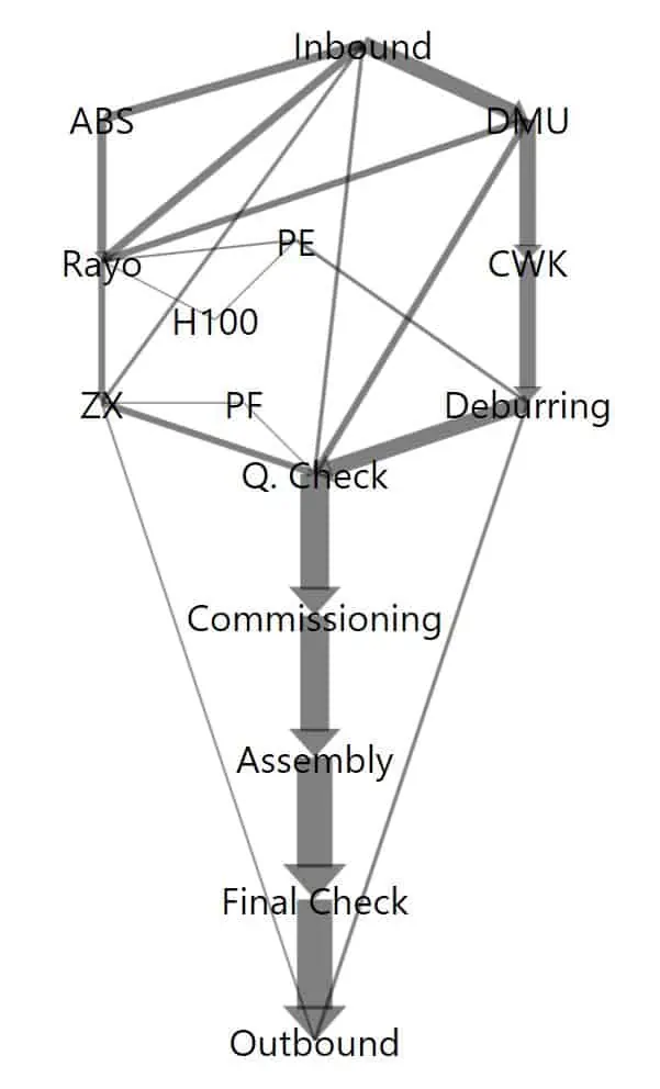
Through this comprehensive consideration of all value streams, synergy potentials in manufacturing that are created by a new part or product become recognizable. In addition, the interactions become recognizable if other parts or products are dropped from the production program at the same time or if the number of units changes significantly. The result is the so-called functional diagram (Sankey diagram) of the factory, which schematically illustrates the flow of all goods through the resources of the factory.
Make-or-buy decisions can also be supported by data and made at an early stage. For example, it makes sense to supply existing, competent or high-margin manufacturing technologies with more units through in-house production. On the other hand, in the course of program changes, resources that are little used will be identified and removed from the machine pool if inefficiencies and thus cost disadvantages arise. It may even be possible to raise purchasing volumes from suppliers above discountable threshold values and thus achieve more favorable conditions.
2. Thinking ahead for change
After planning is before planning. This principle also applies to manufacturing processes and should be considered by any engineer. Product life cycles are becoming noticeably shorter in mechanical engineering too. This is noticeable in factory engineering. Lastly, modularization, adaptability, and scalability in production technology have been among the top ten goals for years in State-of-the-Art factory engineering.
In practical terms, this also means a constant change in the production layout. Those who not only recognize the interrelationship between value stream and layout but can also shape it, are well advised. Two main structural indicators guide manufacturing engineers in evaluating solutions,
Space consumption of the manufacturing process
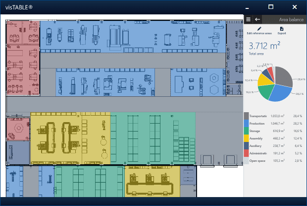
For example, the relative space consumption for various production functions such as manufacturing, assembly, logistics, and storage is an indicator of how efficiently the available space is used. Knowledge objectives in the manufacturing engineering process could be:
- How does the ratio of manufacturing and assembly to logistics space develop in a multi-year comparison?
- What percentage of the space is used for value creation e.g. in assembly lines?
- What percentage of the space is currently available for new projects or expansions?
Transport effort in manufacturing
The other main indicator is the transport effort. In manufacturing engineering, it is easy to measure if the flows of goods and the resources involved are known and located in a scaled layout model. If the intensity of the flows of goods is the same, only the distances to be covered between the resources determine the transport effort. Thus, the transport effort can be used as a structural metric to assess the layout quality of an industrial manufacturing layout solution.
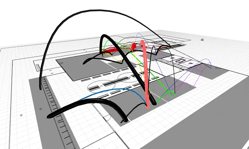
In addition, there are heuristics that help in finding good arrangements for minimal transport effort, e.g.
- modified triangle method (computer-aided with visTABLE®),
- Hungarian method,
- circular method,
- gravity line method.
Use of scenarios in the manufacturing engineering process
The evaluation of these key figures provides an important answer to manufacturing engineers: Will the current factory structure still support the expected change in the production program? The need for action becomes apparent at an early stage.
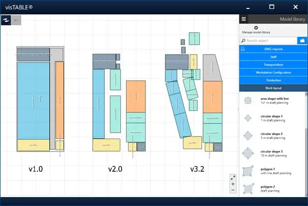
In addition, rough target scenarios can be developed in advance for changes in the production program. This provides greater certainty as to which changes in the production process will require the factory structure to be adapted and how. In the end, the preconceived (target scenarios) can be quickly planned and implemented on the basis of the existing (actual scenario) as soon as the change actually becomes apparent.
3. Use digital factory models for manufacturing engineering
The above considerations make it clear that a factory model is needed that meets the requirements. This should not only contain the actual situation (in the sense of a “digital twin”), but should also be meaningful with regard to the target scenarios. A CAD drawing is therefore not sufficient.
Rather, hierarchical, modular modeling for the factory layout is helpful. In this way, change scenarios can be modeled on a (rough) block layout level without having to change the actual situation in the model, which is naturally represented in fine layouts. Furthermore, factory modules made self-sufficient by the hierarchy can be developed independently and inserted into the model at the given time. For this purpose, the value streams must follow the structure of the model.
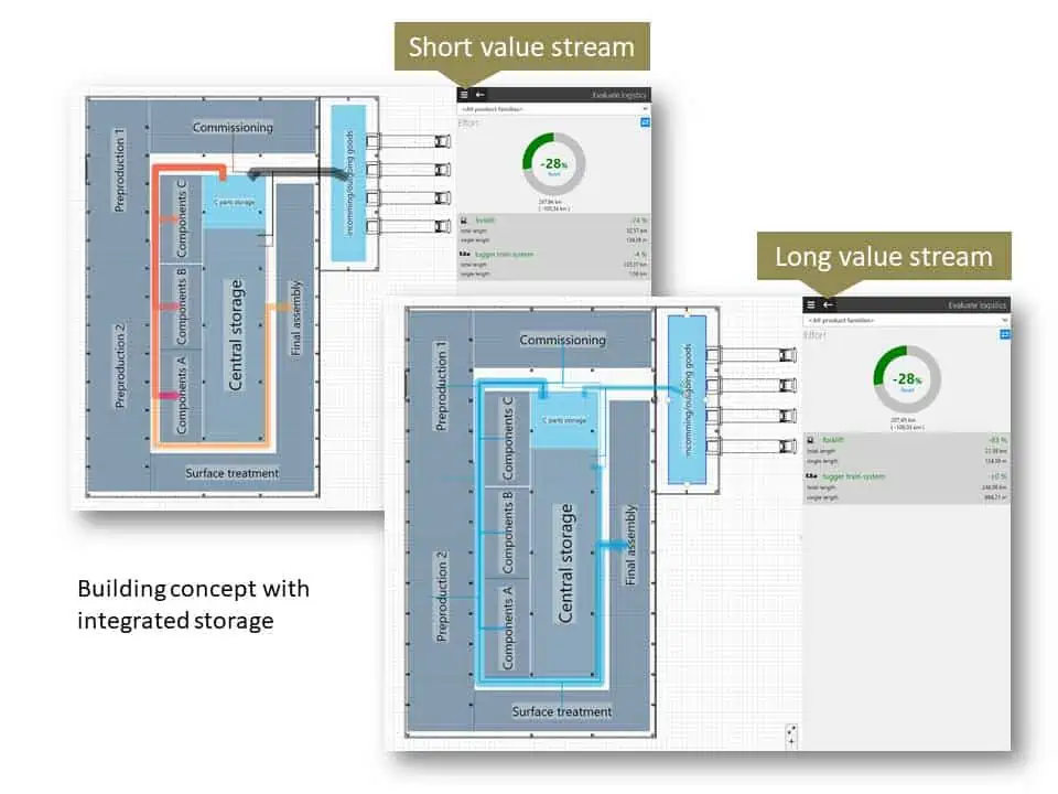
To master the resulting complexity, it is valuable if the factory model digitally represents the value stream and layout and makes their interactions clear. The following blog post focuses on this interrelationship vividly using the example of decision-making for a warehouse concept.
Integrative treatment of value stream and production layout reduces material handling.
Please see the blog:
Conclusion
A holistic design of manufacturing technology always includes not only the actual manufacturing process but also the resources affected by it and thus the production layout. To keep this under control, digital factory models are used that not only depict the current state of value streams and layout but also make future scenarios assessable. Structural indicators such as space consumption and transport costs guide the industrial engineer in evaluating solutions.
Related topics:
