Have you ever been in this situation – you come from industry or especially from mechanical engineering and new machinery or new equipment is to be installed in your manufacturing facility? Is the existing assembly line to be adapted due to a product change? The construction of a new factory is scheduled. Maybe even at a new location?
The Task – Design a Manufacturing Plant Layout
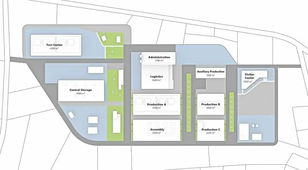
A drawing or plot plan is needed to provide decision-makers with a tangible idea that eventually leads to a decision. Besides, many economic and planning calculations, including factory plans, structural design, equipment, and more, presenting a feasible and detailed depiction of the endeavor is key!
It’s not every day that you are assigned the task of plant engineering like that! To prepare you for the next time your boss approaches you with such a challenge, I want to provide you with a brief six-step guide. I’m sure you’ll benefit greatly from my advice and breeze through creating the draft.

Step 1: What is the aim of Plant Layout Engineering?
Essentially, there are two main aspects you have to keep in mind:
- Determining the feasibility
- Presenting the results
Probably both aspects come into play. Most of the time, feasibility can be examined quite easily and quickly in a facility plan. However, when it comes to presenting the results, the requirements are usually higher. Why is that, you might ask. The reason is quite simple: An abstract or technical model is sufficient for a planner to examine the feasibility, whereas the result often has to be presented to a larger audience in a way that’s easy to grasp.
At this point, you should answer the following questions:
- Should the design be presented analog or digitally?
- Should it be displayed in 2D or 3D?
Now, you may think – of course digitally and in 3D, maybe even with VR. That’s pretty ambitious and would leave quite the impression. Often though, you’ll have to balance the benefit and the effort. One’s own skills and the tools available are what is more important here. This brings us straight to the next point.
Step 2: What tool do I use for the Design of a Plant Layout?
Just by using scissors and paper or by drawing, you can achieve a draft very quickly and easily plan in variants. Sometimes you’ll even face special requirements when it comes to innovatively presenting the result like wooden models often used in architecture.
What matters, in the end, is that you can complete the plan in the given time. The following diagram gives you a selection of options available for a plant layout study or plant planning for the analysis of different configurations.
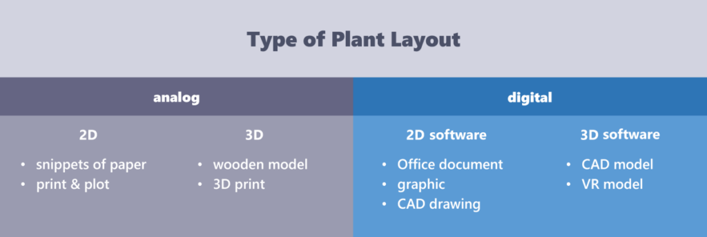
Since there are countless tools for designing floor plans, the terms used simply indicate categories. From experience, however, I can give a clear recommendation: the easier and more intuitive the tool is in usage, the faster and more successfully you will reach your goal.
Surely, you have already used one or the other tool for a plant design and can assign it to the above pillars. At this point, I agree with all those who thought that digital and 3D were the way to go. In the future, this might always be possible. Right now though, the effort seems to be very high compared to the benefit. What is the appropriate tool (I have given my recommendation on this)? How quickly can I familiarize myself with it and design layouts? At this point, the question arises: which data are already available and which do I have to gather myself?
Step 3: What data can be used for Plant Layout Engineering?
Of course, this cannot be answered across the board, as it depends very much on the planning content. In most cases, however, there is some data, either on paper or digitally as a pdf or even in a CAD format.
Parametric statistics should also be considered. Parametric statistics is a branch of statistics that assumes that sample data come from a population that can be adequately modeled by a probability distribution with a fixed number of parameters.
What is exciting about existing data, is the question of topicality. Here it is advisable to randomly check the data by applying control measurements. The accuracy of the data often plays a role here.
Data on the property:
When it comes to the current or future location, it is quite easy to save an image of the map service provider (e.g. Google Maps). This not only shows the property but also the surrounding area. However, please pay attention to the terms of use of the respective map provider. In addition, you can usually obtain the property data digitally (pdf) from the land registry office. Ideally, a detailed master plan may already exist that can be used as a basis. The master plan usually contains the outlines of the existing buildings with their dimensions.
Data on the facility:
In most cases. data is already available. For older buildings, there are usually drawings of the top view and sometimes also of a sectional perspective, such as floor plans. These drawings can either be copied or a photo can be taken and used as an image in digital form. If the buildings are not much older than the year 2000, there is a good chance that the data is also available digitally, in CAD format, or as a PDF. From the year 2010 onwards, data sets of the facilities in a 3D CAD format (.dwg, .step, or .ifc) should definitely exist. As a rule, the architect also provides these to the client with the handover of the documentation or submits them on request.
When it comes to data, the topic of building services equipment is quite fascinating. Especially in floor plans where height plays a role, the positions of pipelines, media routes, and exhaust air pipes are important. Information about piping design is an elementary part of a facility plan. A piping system is crucial to any process plant; hence it needs to be designed with precision and care. In the best case, this information is part of the project data and is stored there. If not, the technology of 3D laser scanning offers a simple and fast way of recording the existing data.
Data on equipment:
The sorts of equipment needed may vary quite a bit. In some cases, digital 2D data on machines and workplaces are already available as files in the DWG or DXF format. Often, these are ready-made models provided by the manufacturer or the data is self-recorded and shows the main dimensions of the respective equipment (length and width). When it comes to new equipment, you will most likely obtain the 3D models from the manufacturer, e.g. in step format. This is important: Make sure that the models are provided in a simplified form (only the outer contour or interference contour) for facility planning. This is a setting the equipment supplier can usually adjust pretty easily when exporting the model in his CAD program.
Data on the processes:
The data on processes is mainly about data that depicts the connection between the equipment. Since the structure of the draft essentially depends on logistical processes, this concerns the material flow data. This material flow data is depicted in the layout e.g. as a spaghetti diagram.
Here, the number of products to be produced and the transport lot sizes that result in the number of transports serve as the data basis. In most cases, this data can be taken from the ERP system. If they are not listed there, they can also be obtained by observation or by contacting the logistics department.
When taking over the data, whether it is a plot of land, buildings, or even equipment, you will definitely come across the topic of the next point.
Step 4: Which Scale do I use?
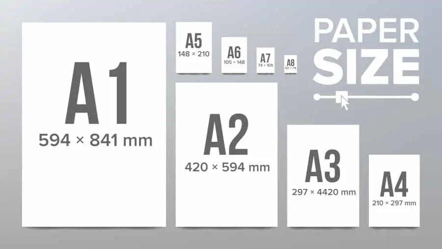
Answering this question is pretty simple. Considering the graphic above, you will always work with the original size when you design the draft digitally. An object with a height of 1m is modeled digitally in the software with a height of 1m, too.
So, when you receive data for the plot, the plant, or the equipment, make sure that these are correctly scaled (to the original size) before importing them. There are always models that were not drafted in the original size.
Especially in the course of globalization, one should also look at the system of measurement. Especially in America, the Anglo-American system of measurement is common. So, if you use the international system of measurement for your draft, you should also take conversion into account when importing the models.
If you want to design the draft analogue though, it is important to choose a suitable scale. This is quite common when you want to print out a digital drawing on paper, for example, or present it in the form of a 3D model. There are recommended scales for printing (e.g. 1:100), which can be used to calculate back to the original size very quickly, or even rulers that already have the conversion included in the scale. Otherwise, you should choose the scale so that the plan also fits the output medium, e.g. on an A3 page. Fortunately, many software systems offer a suitable preview to help you choose the scale.
After the step-by-step determination of the objective, and the selection of the tool and the data, the preparations for a plant layout have been largely completed. Now it is time for the actual creation.
Step 5: How do I build my Layout?
At this point, all the data available is usually taken and included. Additionally, one’s own evaluation is added, and grown structures are created very quickly. This may cause the draft to no longer be manageable, or it is difficult to maintain an overview.
Layer
Since many models and layouts contain layers that are used in different ways, this phase might very well be the most chaotic one. Layers, however, are meant to organize the draft according to function and purpose.
With regard to layer designations, one can fall back on existing standards, such as VDI 6027.
It is further recommended to structure the functions hierarchically within the layer designations. This allows the layers to be clearly grouped in a list according to the main function, function and sub-function. Here are some examples:
- Building—support—wall
- Building—support—column
- Building—extension—wall
- Building—extension—door
- Logistics—storage—shelves
- Logistics—storage—container
- Production—Manufacturing—Machining machines
- Production—Assembly—Working tables
- …
Layers are particularly important when it is necessary to hide or show objects, or to protect them against accidental movement. It is best to set up your layer structure before the first object. Then you can assign them to the layers directly with the first objects in the layout.
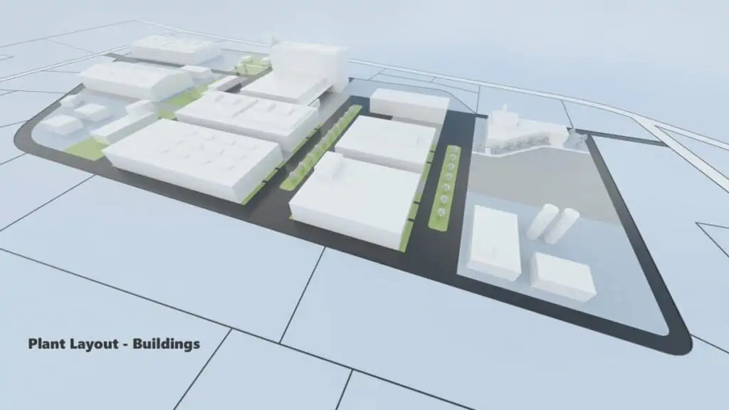
Note: The layers make it possible to add different levels of detail to the object. In this way, you can also develop a layout from 2D concept planning to 3D layout planning.
Object designation
When importing or creating objects, they should be given a unique object designation (object name) in addition to the assignment to the layers. Firstly, this facilitates the search for the objects in the layout and, secondly, enables the assignment to further planning functions.
The object name could, for example, be composed of the manufacturer’s name, the type designation and the inventory number:
- Manufacturer Type Designation_Number
Area Types and other Attributes
Furthermore, area types should be assigned to the objects. On this basis, you can then directly derive an area balance. However, you should first consider what area types to use. Examples of area types could be:
- Production
- Assembly
- Warehouse
- Administration
- Transport
- Social
- Expansion/open space
Another idea is to assign attributes to the objects that serve as an overview or as a basis for planning. The following attributes are possible, among others:
- Compressed air connection – bar – 6
- Water consumption – litres/h – 10
- Machine hourly rate – Euro – 20
- Cost center number
Storage and Naming
Once you have made initial progress, the next question arises when saving your project: where should it be stored and, more importantly, how should it be named? The storage location is usually determined by a folder structure in the company’s file system. In addition to storage in the file system, database-supported data management systems can also be used. In any case, it is important that the designs are not lost due to a hardware defect. Therefore, it is advisable to not only store the data locally, e.g. on your laptop, but also to save a version in a cloud or network environment secured by a backup.
When storing in the file system, there are three major aspects to consider:
- Status in the planning cycle
- Hierarchies
- Variants
In a data management system, the previously mentioned aspects can be mapped via attributes – the file name may play a subordinate role here.
The status in the planning cycle refers to the current processing status of the project. There should be a fixed filing structure for the inventory plans, including control of the access rights. Up-to-date pdfs containing the as-built plans should always be filed.
Planning cycles can look like this, for example:
- EXISTING ➔ PLANNING ➔ RELEASED ➔ IMPLEMENTED ➔ EXISTING or
- EXISTING ➔ CONCEPT PLANNING ➔ ROUGH PLANNING ➔ DETAILED PLANNING ➔ RELEASED ➔ IMPLEMENTED ➔ STOCK
Hierarchies are used to break down larger layouts into sub-layouts and to support planning from draft to detailed and vice versa. Different hierarchy levels can be, for example:
- FACTORY ➔ HALL ➔ PRODUCTION AUTHORITY/SECTION/DEPARTMENT ➔ WORKPLACE or
- FACTORY ➔ FACTORY AREA/SECTION ➔ HALL ➔ HALL AREA/SECTION/DEPT. ➔ DEPARTMENT ➔ PRODUCTION AREA/SECTION ➔ WORKPLACE
Variant designations should be distinguished clearly from the status in the planning cycle, such as:
- M8-H04-LINE02_PLANNING210208_v02
- M8-H04-LINE02_EXISTED (M8-H04-LINE02_EXISTED210208 in archive folder)

Conclusion
It takes more than just software and a little time to design a ready-to-use plant layout. You should think about the approach and the implementation in advance in order to achieve the goal successfully. I hope the guideline I provided will assist you in plant planning.
Related topics:
- Rough layout vs. fine layout
- Do I need 3D for layout planning?
- The plant floor plan – just a drawing?